
Submittal Sheet
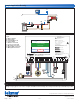

Sample Mechanical diagram
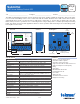
Sample Electrical diagram
670
_
C - 10/16 2 of 2 © 2016 tekmar
Tel: (250) 545-7749 • Fax: (250) 984-0815
tekmarControls.com
All specications are subject to change without notice.
Sample Application Drawing
Legend
B1 = Mod-Con Boiler
BP = Boiler Pump
M1 = Actuating Motor 741
P1 = System Pump
S1 = Outdoor Sensor 070
S2 = Snow / Ice Sensor 090
S3 = Mix Supply Sensor 082
S4 = Boiler Supply Sensor 082
V1 = Mixing Valve 710 Series
070
670
BP
P1
M1
S4
S1
S3
S2
V1
B1
Com
Close
Open
TT–+
20
Mod Boiler
19
WiFi Snow Melting Control 670
Boiler & Mixing / Electric
Power 115 V (ac) ±10%, 60 Hz, 20 VA
Relays 230 V (ac) 5 A 1/3 hp
Var. Pump 230 V (ac) 2.4 A
1084-01
Designed and assembled in Canada
Date Code
H2055A
1 kΩ max 1 kΩ max
Opn
3
Var
2
–
Mix V/mA
1
+
Pwr
4
Mix
Cls
5
Blu
8
Yel
9
Brn/
10
Slab
Man
11
Melt
C
12
Blk/
7
Com
Red
6
Boiler 1
21
Stage 1
Boiler 1
Stage 2
Heat
Relay
System
Pump–
22
+
23 24 25
Do Not Apply Power
Mix
15
Sup
Com
16
Boil
17
Out
18
Com
14
tN4
13 282726
Power
29
L
30
N
For product literature:
Pour la documentation du produit:
Para la literatura del producto:
tekmarControls.com
Disconnect all power before opening.
WARNING
Coupez l'alimentation avant l'ouverture.
ATTENTION
Desconecte la electricidad antes de abrir.
ADVERTENCIA
Signal wiring must be rated at least 300 V.
Le câblage du signal doit être d'une capacité d'au moins 300 V.
Cableado de señal debe tener una
calificación mínima de 300 V.
Contains WiFi transceiver:
FCC ID: Z64-CC3100M0DR1, IC: 4511-CC3100M0DR1
Meets Class B: FCC Part 15B, ICES-003
Manual Melt
Time Left
- - : - - hrs
Outdoor
32 °F
Settings Status
System is Melting
Stop
10:30 AM
Warming Up
P1
V1
M1
N
L
S4
S3
B1
S2
S1
R
C
This Submittal is not intended to provide full installation instructions and safety information. In order to avoid property
damage or injury, please refer to the complete installation manual and product safety information provided with the product.