
Application Guide


4 of 20
© 2016 tekmar 670
_
A - 10/16
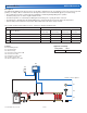
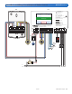
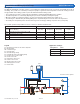
Dedicated Boiler and Mixing A670-2 Mechanical
Application Settings
Setting Name Value
Application Mode Boiler+Mix
B1 = Modulating Boiler
M1 = Actuating Motor 741
P1 = System Pump
P2 = Boiler Pump
S1 = Snow/Ice Sensor 090 or 094
S2 = Snow Sensor 095
S3 = Slab Sensor 072 or 073
S4 = Outdoor Sensor 070
S5 = Boiler Supply Sensor 082
S6 = Mix Supply Sensor 082
X1 = Transformer 009
V1 = 3-Way Mixing Valve 710 through 714
Legend
670
Snow/Ice Sensor Options
S4
S5
S6
P1
P2
V1
M1
B1
S1
S2
S3
Description
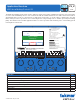
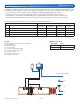
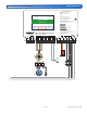
The WiFi Snow Melting Control 670 operates a boiler and a mixing valve that is dedicated for the snow melting system. The
boiler is piped in primary-secondary to the system to allow constant flow rates through the low-mass boiler. The entire system
is filled with glycol to prevent freezing.
• The system and boiler pumps operate continuously when heating the slab during melting/idling/storm operation.
• The mixing valve position is adjusted to 100% open unless providing boiler return protection.
• The slab temperature is controlled by modulating the boiler firing rate or cycling the boiler on and off.
• The slab target is determined by the melting/idling/storm setpoint and by the measured outdoor air temperature.
• Optional slab protection limits the temperature differential between the boiler supply and slab.
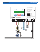
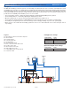
The system operation is dependent on sensor selection, as listed in the table below.
Sensor options Operation methods
Sensor
Sensor Model(s)
Auto Start/
Auto Stop
Auto Start/
Timed Stop
Manual Start/
Timed Stop
Slab Temperature
Control
S1 Automatic Snow/Ice Sensor 090 or 094 • – • •
S2 Aerial Snow Sensor 095 – • • –
S3 Slab Sensor 072 or 073 – – • •
S2+S3 Aerial Snow Sensor 095 and Slab Sensor 072/073 – • • •