
Application Guide


© 2016 tekmar 670
_
A - 10/16
19 of 20
20
Mod Boiler
19
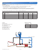
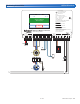
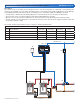
WiFi Snow Melting Control 670
Boiler & Mixing / Electric
Power 115 V (ac) ±10%, 60 Hz, 20 VA
Relays 230 V (ac) 5 A 1/3 hp
Var. Pump 230 V (ac) 2.4 A
1084-01
Designed and assembled in Canada
Date Code
H2055A
1 kΩ max 1 kΩ max
Opn
3
Var
2
–
Mix V/mA
1
+
Pwr
4
Mix
Cls
5
Blu
8
Yel
9
Brn/
10
Slab
Man
11
Melt
C
12
Blk/
7
Com
Red
6
Boiler 1
21
Stage 1
Boiler 1
Stage 2
Heat
Relay
System
Pump–
22
+
23 24 25
Do Not Apply Power
Mix
15
Sup
Com
16
Boil
17
Out
18
Com
14
tN4
13 282726
Power
29
L
30
N
For product literature:
Pour la documentation du produit:
Para la literatura del producto:
tekmarControls.com
Disconnect all power before opening.
WARNING
Coupez l'alimentation avant l'ouverture.
ATTENTION
Desconecte la electricidad antes de abrir.
ADVERTENCIA
Signal wiring must be rated at least 300 V.
Le câblage du signal doit être d'une capacité d'au moins 300 V.
Cableado de señal debe tener una
calificación mínima de 300 V.
Contains WiFi transceiver:
FCC ID: Z64-CC3100M0DR1, IC: 4511-CC3100M0DR1
Meets Class B: FCC Part 15B, ICES-003
Manual Melt
Time Left
- - : - - hrs
Outdoor
32 °F
Settings Status
System is Melting
Stop
10:30 AM
Warming Up
20
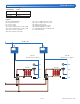
Mod Boiler
19
WiFi Snow Melting Control 670
Boiler & Mixing / Electric
Power 115 V (ac) ±10%, 60 Hz, 20 VA
Relays 230 V (ac) 5 A 1/3 hp
Var. Pump 230 V (ac) 2.4 A
1084-01
Designed and assembled in Canada
Date Code
H2055A
1 kΩ max 1 kΩ max
Opn
3
Var
2
–
Mix V/mA
1
+
Pwr
4
Mix
Cls
5
Blu
8
Yel
9
Brn/
10
Slab
Man
11
Melt
C
12
Blk/
7
Com
Red
6
Boiler 1
21
Stage 1
Boiler 1
Stage 2
Heat
Relay
System
Pump–
22
+
23 24 25
Do Not Apply Power
Mix
15
Sup
Com
16
Boil
17
Out
18
Com
14
tN4
13 282726
Power
29
L
30
N
For product literature:
Pour la documentation du produit:
Para la literatura del producto:
tekmarControls.com
Disconnect all power before opening.
WARNING
Coupez l'alimentation avant l'ouverture.
ATTENTION
Desconecte la electricidad antes de abrir.
ADVERTENCIA
Signal wiring must be rated at least 300 V.
Le câblage du signal doit être d'une capacité d'au moins 300 V.
Cableado de señal debe tener una
calificación mínima de 300 V.
Contains WiFi transceiver:
FCC ID: Z64-CC3100M0DR1, IC: 4511-CC3100M0DR1
Meets Class B: FCC Part 15B, ICES-003
Manual Melt
Time Left
- - : - - hrs
Outdoor
32 °F
Settings Status
System is Melting
Stop
10:30 AM
Warming Up
50
51 52 53
Stage1/ Stage 2/
Boil Enbl Setp Enbl
75
76 77 78
Demand Demand
DHW Setpoint
54 55
DHW Primary
10 A
max
79 80 81 82
N
Pump NPump
tN4
Made in Canada
8 VA 1 VA
Boil Sens Sup / Ret
H7010A
Off / DHW Sensor
Off / tekmar Stager
Boilers On-Off / Mod
Off / Rotation
Meets Class B: Canadian
ICES & FCC Part 15
Powered
Outputs
24 V (ac)
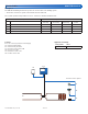
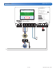
Universal Reset Module 423
Item
Menu
tektra 1006-01
Demands: 20 - 260 V (ac)
Relay Rating: 115 V (ac) 5 A
71
72 73 74
DHW 24 V (ac)
/
57 58 59 60 6156
C
C
tN4
Mod2 (dc)Mod1 (dc)
6564
C3
C1+–
C
+–
tN4
62 63
C2 tN4tN4
66 67
DHW
Com
Boiler
68 69
Boil Com
70
Out
Do not apply power
Test
1 2 3
Vlv R
No Power
Mixing Expansion Module 444
Variable Speed / Floating Action /
Modulating
Made in Canada
Signal wiring
must be rated at
least 300V / 90°C
Cut for mA output
5
R
6
R
41
tN4
7
Mod
+
8
Com
9
Mix
PowerClsOpn
Sys
Pmp
2
C
3
R
No Power
Date Code
1
tektra 1019-01
1
Power Manager 346
For product literature:
www.tekmarcontrols.com
Boiler Bus 0 Demand Power
Aux Pump 1
Aux Pump 2
Aux Pump 3
tN4
Bus 1 Demand
Bus 2 Demand
Bus 3 Demand
Meets Class B: Canadian
ICES & FCC Part 15
Caution! Disconnect All
Power before Opening
24 V (ac) Fuse: T2.5 A 250 V
H7011A
Relay Power
27 28
N
L
Aux Pump 2
29 30
N
Pmp
Aux Pump 3
31 32
N
Pmp
For product instructions, see brochure
Input Power: 115 V (ac) ±10% 60 Hz, 12 A
All Loads Using Input Power: 11.5 A
Relay Ratings: 115 V (ac) 5 A
Relay Power: 115 V (ac) ±10% 60 Hz, 10 A
Demands: 20 to 260 V (ac) 2 VA
Supply wires 90°C/105°C
See manual
Boil Bus
0
16 17
Demand
Bus
3Bus
2
18
Dem DemDem
19
Bus 1
20 21
Demand
227
tN4
56
t
N
4C C
2
Boil 0
11
tN4
910
2
CC
15
tN4
13 14
3
Com
Aux
Pmp1
4
RR R R
3
Aux
Pmp2
8
Aux
Pmp3
12
Limited power available, see wiring brochure
Room Occ
Room UnOcc
0Boil
1
2
3
1
3
11
9
7
5
12
10
8
6
4
2
Schedule
Member
Input Power
23 24
N
L
Aux Pump 1
25 26
N
Pmp
RC
Com
Open
Close
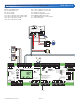
A670-8 Electrical
670 Application Settings
Setting Name Value
Application Mode PWM Zone
Outdoor Sensor tekmarNet
Boiler Type Control
S1a
S1b
P1
P2
L
L
N
N