
Application Guide
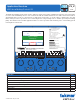


10 of 20
© 2016 tekmar 670
_
A - 10/16
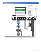
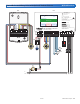
Shared Boiler and Mixing Injection Pump
A670-5 Mechanical
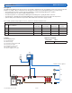
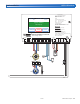
Application Settings
Setting Name Value
Application Mode Mixing
Mixing Type Injection
Boiler Type Enable
A1 = Normally Closed Freeze Protection Aquastat
B1 = Boiler Enable
HX = Heat Exchanger
P1 = System Pump
P2 = Heat Exchanger Pump
P3 = Variable Speed Injection Mixing Pump
S1 = Snow/Ice Sensor 090 or 094
S2 = Snow Sensor 095
S3 = Slab Sensor 072 or 073
S4 = Outdoor Sensor 070
S5 = Boiler Return Sensor 082
S6 = Mix Supply Sensor 082
V1 = Globe Valve
Legend
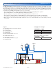
Sensor options Operation methods
Sensor
Sensor Model(s)
Auto Start/
Auto Stop
Auto Start/
Timed Stop
Manual Start/
Timed Stop
Slab Temperature
Control
S1 Automatic Snow/Ice Sensor 090 or 094 • – • •
S2 Aerial Snow Sensor 095 – • • –
S3 Slab Sensor 072 or 073 – – • •
S2+S3 Aerial Snow Sensor 095 and Slab Sensor 072/073 – • • •
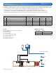
670
Snow/Ice Sensor Options
S4
S5
P2 P1
S6
P3
HX
S1
S2
S3
A1
V1
Description
The WiFi Snow Melting Control 670 operates a snow melting zone warmed from a heat source that is shared with other loads in
a building. The system uses a variable speed injection pump to regulate the water temperature and a heat exchanger isolates
the glycol-filled snow melting system loop from the water-filled main heating system.
• The system pump operates continuously when heating the slab during melting/idling/storm operation.
• The slab temperature is controlled by adjusting the speed of the variable speed injection pump.
• When the variable speed injection pump is on, the heat exchanger pump and the boiler enable are on.
• The slab target is determined by the melting/idling/storm setpoint and by the measured outdoor air temperature.
• A normally-closed aquastat protects the heat exchanger from freezing by shutting off power to the system pump.
The system operation is dependent on sensor selection, as listed in the table below.