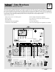
- Data Brochure D 667 Snow Detector & Melting Control 667 09/02 The Snow Detector & Melting Control 667 is a microprocessor-based control which operates a snow melting system. The control can operate automatically when a Snow/Ice Sensor 090 is installed or the user can manually enable and/or disable the system. The 667 controls a variable speed injection pump to provide both boiler and slab protection.
How To Use The Data Brochure This brochure is organized into four main sections. They are: 1) Sequence of Operation, 2) Installation, 3) Control Settings, and 4) Troubleshooting. The Sequence of Operation section has 6 sub-sections. We recommend reading Section A: General of the Sequence of Operation, as this contains important information on the overall operation of the control. Then read to the sub-sections that apply to your installation.
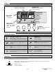
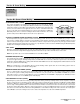
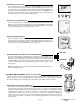
Display Item Field Number Field Displays an abbreviated name of the selected item Displays the current value of the selected item Melt Demand Idle Demand WWSD Minimum Maximum Water Melting Menu Field Displays the current menu 2 Status Field Displays the current status of the control's inputs, outputs and operation Buttons Selects Menus, Items and adjusts settings Symbol Description Ovr Mixing Device Output Scale Shows output of injection pump.
Sequence of Operation Section A Section B Section C Section D Section E General Operation Page 4 Snow Melting Page 5 - 6 Boiler Operation Page 7 - 8 Melting Enable/ Disable Page 8 - 10 Melting Operation Page 11 Section F Idling Operation Page 12 Section A: General Operation POWERING UP THE CONTROL When the Snow Detector & Melting Control 667 is powered up, the control displays all LCD segments for 2 seconds, then the control type number in the LCD for 2 seconds.
Section B: Snow Melting Section B1 General Snow Melting Section B1: General Snow Melting SLAB PROTECTION (∆T MAX) The control can limit the rate at which heat is applied to the zone through the ∆T MAX setting. The ∆T (delta T) is the temperature difference between the snow melting supply temperature and the snow melting return temperature. By limiting this temperature difference, the rate at which heat is applied to the zone can be controlled and thermal stresses in the slab can be minimized.
STATUS (STATUS) While in the View menu there are a number of items available to determine the current status of the system. To view the current status of the system, select the STATUS item in the View menu. • STRT The word STRT is displayed after the snow melting system has been manually enabled. It is displayed until the system reaches its slab target temperature. If the system is at its slab target temperature, STRT is displayed for five seconds after the snow melting system has started operation.
Section C: Boiler Operation Section C1 Section C2 Section C3 Boiler Supply Sensor Boiler Return Sensor No Boiler Sensor Section C1: Boiler Supply Sensor BOILER SENSOR ON THE SUPPLY (Boil SENS = SUP) When operating a boiler that is dedicated to a snow melting system, the 667 is designed to operate the boiler as efficiently as possible. The boiler is cycled based on the mixing supply fluid temperature. This is to provide longer and more efficient boiler cycles.
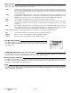
Off If the AUTO differential is selected, the 667 automatically adjusts the differential setting under the current load conditions to avoid short cycling. Differential On Snowmelt Load Auto Differential (AUTO) Time Section C2: Boiler Return Sensor BOILER SENSOR ON THE RETURN (Boil SENS = RET) The boiler sensor should be located on the boiler return if the 667 is one of many controls that can call for boiler operation.
Start Button on the Control The snow melting system is enabled by pressing the Start button on the control while in the View menu. The control then displays the RUN TIME setting to allow the user to adjust it. Once the snow melting system is enabled, the word STRT is displayed for at least 5 seconds in the STATUS item while in the View menu. If the Start button on the control is pressed while the system is already melting and up to temperature, the running time counter is reset to the RUN TIME setting.
Section D2: Snow Melting Disable The snow melting system can be disabled manually or automatically. A melting disable signal applied to the control takes the zone out of the melting mode. Once the snow melting system is disabled, the zone operates in the idling mode. The idling mode allows the zone to be operated either at a lower temperature or turned off.
Section E: Melting Operation Section E1 General Melting Operation Section E1: General Melting Operation In order for the snow melting system to be started, one of the methods described in section D1 must be used. Once a melting enable signal is applied and the system is not in WWSD or CWCO, the melting mode begins. When the control is in the melting mode, the Melting pointer is visible in the View menu. The MELT setting in the Adjust menu sets the slab surface temperature.
Section F: Idling Operation Section F1 General Idling Operation Section F1: General Idling Operation When the snow melting system starts from a cold temperature, the time required for the system to reach the melting temperature may be excessive. To decrease this start up time, the 667 has an idling feature which can maintain the system at a lower temperature. This feature is also useful for preventing frost and light ice formation.
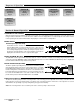
• Run wire from other system components (pumps, boiler, etc.) to the control. • Run wires from the 115 V (ac) power to the control. Use a clean power source with a minimum 15 A circuit to ensure proper operation. Multi-strand 16 AWG wire is recommended for all 115 V (ac) wiring due to its superior flexibility and ease of installation into the terminals. STEP FOUR –––––––––– ELECTRICAL CONNECTIONS TO THE CONTROL The installer should test to confirm that no voltage is present at any of the wires.
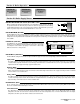
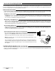
If a variable speed injection pump is used, connect one of the wires from the variable speed injection pump to the Var terminal (1) on the 667. Connect the Pwr Mix terminal (2) to the live (L) side of the 115 V (ac) power source. The other wire on the variable speed injection pump must be connected to the neutral (N) side of the 115 V (ac) power supply. Sensor and Unpowered Input Connections Do not apply power to these terminals as this will damage the control.
tekmar Net™ (tN2) Device A Remote Display Module (RDM) 040 or Remote Start / Stop Module 039 can be connected to the tekmar Net™ (tN2) input. Connect the Com terminal from the appropriate tN2 device to the Com terminal (9) on the 667. Connect the tN2 terminal from the appropriate tN2 device to the tN2 terminal (10) on the 667. 9 10 Note: The wires from the RDM and Remote Start / Stop Module are polarity sensitive. The tN2 device does not operate correctly if the wires are reversed.
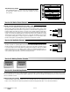
System Pump (System Pmp 2 ) If a pump is connected to the System Pmp 2 terminals (17 and 18), make sure power to the pump circuit is off and install a jumper between the System Pmp 2 terminals (17 and 18). When the circuit is powered up, the pump should turn on. If no response occurs, check the wiring between the terminal and the pump and refer to any installation or troubleshooting information supplied with the pump. If the pump operates properly, disconnect the power and remove the jumper.
To change the access level, set the DIP switch to the unlocked, or down position. The current access level of the control or tekmar Net™ tN2 device is viewed in its Miscellaneous (Misc) menu. While viewing the access level, use the ▲ and ▼ keys to select between the Limited (LTD), User (USER), Installer (INST) or Advanced (ADV) access levels. To lock the access level, select the appropriate access level in the Miscellaneous (Misc) and move the DIP switch from the unlocked position to the locked position.
667 View Menu (2 of 2) Description Se ct LT ion D U SE IN R S AD T V Item Field Access Level Range Current mixed return water temperature as measured by the mixing return sensor. B1 Mix Ret Sensor present Current mixed ∆T difference between the mixed supply sensor and the mixed return sensor. B1 ∆T MAX ≠ OFF Current boiler supply water temperature as measured by the boiler sensor. A C1 Boil SENS = SUP Current boiler return water temperature as measured by the boiler sensor.
667 Adjust Menu (2 of 2) Se ct LT ion D U SE IN R S AD T V Item Field Access Level B1 A C B1 Description The Cold Weather Cut Off temperature for the snow melting system. The maximum supply water temperature for the mixing system. The location of the boiler sensor. This affects operation of the boiler contact. The maximum ∆T for the snow melting system.
667 Monitor Menu (1 of 2) Note: To clear the recorded information in the specific item field, press and hold ▲ and ▼. Description Range LT D U SE IN R S AD T V Item Field Access Level The highest recorded outdoor air temperature since this item was last cleared. -67 to 149°F (-55 to 65°C) The lowest recorded outdoor air temperature since this item was last cleared. -67 to 149°F (-55 to 65°C) The highest recorded temperature at the slab sensor since this item was last cleared.
667 Monitor Menu (2 of 2) Note: To clear the recorded information in the specific item field, press and hold ▲ and ▼. Access Level Description Range LT D U SE IN R S AD T V Item Field This item is an adjustable warning. If the slab temperature does not reach the slab target temperature within the set time, the control displays a warning message. 1 to 24 hr, OFF Default = OFF The number of times that the microprocessor in the control has reset since this item was last cleared.
667 Misc (Miscellaneous) Menu (1 of 1) Description Range LT D U SE IN R S AD T V Item Field Access Level The units of measure that all of the temperatures are to be displayed in by the control. °F, °C The operating mode for the back lighting on the LCD as well as time of keypad inactivity until the control automatically returns to the default display. OFF, 30 sec, ON The access level that is to be used by the control.
Testing the Control The Snow Detector & Melting Control 667 has a built-in test routine which is used to test the main control functions. The 667 continually monitors the sensors and displays an error message whenever a fault is found. See the following pages for a list of the 667’s error messages and possible causes. When the Test button is pressed, the test light is turned on. The individual outputs and relays are tested in the following test sequence.
667 Error Messages (1 of 3) Error Displayed Description of Error The control was unable to store a piece of information into its EEPROM. This error can be caused by a noisy power source. The control will display the error message and will continue to operate as normal. Pressing either the Menu or Item button will clear this error. The control was unable to read a piece of information stored in the Adjust menu.
667 Error Messages (2 of 3) Error Displayed Description of Error The control is no longer able to read the mixing supply sensor due to an open circuit. In this case, the control does not operate the snow melting system. Locate and repair the problem as described in the Data Brochure D 070. To clear the error message from the control after the sensor has been repaired, press either the Menu or Item button. The control is no longer able to read the mixing return sensor due to a short circuit.
667 Error Messages (3 of 3) Error Displayed Description of Error The control is no longer able to read the water detection circuit due to an open circuit. In this case, if the control is currently in the Melting mode, the control will finish the snow melting cycle. The snow melting system can only be operated using an external melt demand, Remote Display Module 040, Remote Start / Stop Module 039 or the Start button on the control. Otherwise, the control will operate as if the Snow / Ice Sensor 090 is dry.
Notes 27 of 28 © 2002 D 667 - 09/02
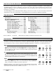
Technical Data Snow Detector & Melting Control 667 Variable Speed Injection Literature Control Packaged weight Dimensions Approvals Ambient conditions — — — — — — Power supply Relays Var. Pump Demand Sensors included — — — — — Optional devices — D 667, A 667, D 001, D 070, E 021, U667. Microprocessor PID control; This is not a safety (limit) control. 3.1 lb. (1400 g), Enclosure A, blue PVC plastic 6-5/8” H x 7-9/16” W x 2-13/16” D (170 x 193 x 72 mm) CSA C US, meets ICES & FCC regulations for EMI/RFI.