
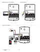
Install Instructions


© 2020 654_D - 02/20 8 of 44
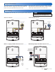
A good quality test meter capable of measuring up to 5,000 kΩ
(1 kΩ = 1000 Ω) is required to measure the sensor resistance. In
addition to this, the actual temperature must be measured with
either a good quality digital thermometer, or if a thermometer
is not available, a second sensor can be placed alongside
the one to be tested and the readings compared.
First measure the temperature using the thermometer and
then measure the resistance of the sensor at the control. The
wires from the sensor must not be connected to the control
while the test is performed. Using the chart below, estimate
the temperature measured by the sensor. The sensor and
thermometer readings should be close. If the test meter reads
a very high resistance, there may be a broken wire, a poor
wiring connection or a defective sensor. If the resistance is
very low, the wiring may be shorted, there may be moisture
in the sensor or the sensor may be defective. To test for
a defective sensor, measure the resistance directly at the
sensor location.
Do not apply voltage to a sensor at any time as damage
to the sensor may result.
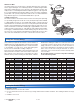
Testing the Sensor Wiring
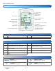
Temperature Resistance Temperature Resistance Temperature Resistance Temperature Resistance
°F °C °F °C °F °C °F °C
-50 -46 490,813 20 -7 46,218 90 32 7,3 34 160 71 1,689
-45 -43 405,710 25 -4 39,913 95 35 6,532 165 74 1,538
-40 -40 336,606 30 -1 34,558 100 38 5,828 170 77 1,403
-35 -37 280,279 35 2 29,996 105 41 5,210 175 79 1,281
-30 -34 234,19 6 40 4 26,099 110 43 4,665 180 82 1,172
-25 -32 196,358 45 7 22,763 115 46 4,184 185 85 1,073
-20 -29 165,180 50 10 19,900 120 49 3,760 190 88 983
-15 -26 139,403 55 13 17,4 3 6 125 52 3,383 195 91 903
-10 -23 118,018 60 16 15, 311 130 54 3,050 200 93 829
-5 -21 100,221 65 18 13,474 135 57 2,754 205 96 763
0 -18 85,362 70 21 11,883 140 60 2,490 210 99 703
5 -15 72,918 75 24 10,501 145 63 2,255 215 102 648
10 -12 62,465 80 27 9,299 150 66 2,045 220 104 598
15 -9 53,658 85 29 8,250 155 68 1,857 225 107 553
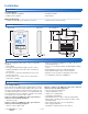
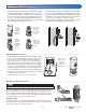
Bottom of
Enclosure 080
Universal
Sensor
Cable Tie
Sensor Well
Retaining
Clip
Universal
Sensor
Immersion Well
If a Universal Sensor is mounted onto 1" (25 mm) diameter L type copper pipe,
there is approximately an 8 second delay between a sudden change in water
temperature and the time the sensor measures the temperature change. This
delay increases considerably when mild steel (black iron) pipe is used. In general,
it is recommended that a temperature well be used for steel pipe of diameter
greater than 1-1/4" (32 mm). Temperature wells are also recommended when
large diameter pipes are used and fluid stratification is present.
Conduit Connection
The Universal Sensor and Universal Sensor Enclosure 080 (sold separately)
are specifically designed to mount onto a 3/8" (10 mm) ID temperature well that
is supplied with an end groove. To install the well, plumb a ‘T’ into the pipe and
fix the well into the ‘T’. The 080 enclosure has a 7/8" (22 mm) back knockout that
must be removed and fitted over the temperature well. The universal sensor is
then inserted into the well and the retaining clip supplied with the enclosure is
snapped onto the well end groove. If the well has a threaded end, the installer
must supply a standard threaded conduit retaining ring. The two wires from
the sensor are connected to the terminal block provided in the enclosure. The
other side of the terminal block is used to connect wires from the control.
Testing the Control Wiring
Testing the Power
-------------------------------------------------------------------------------------- --------------------------------------------------------------------------------------
1. Remove the front cover from the control.
2. Use an electrical test meter to measure (ac) voltage between the R and C terminals. The reading should be 24 V (ac)
+/– 10%.
3. Install the front cover.