
Install Instructions


33 of 44 © 2020 654_D - 02/20
Application Modes
Pulse Width Modulation Operation
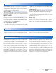
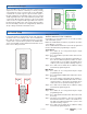
Slab Protection
In a hydronic snow melting system, the boiler or heating
plant capacity may be much larger than the load of the snow
melting zones. This can result in large temperature differentials
between the supply water temperature and the slab creating
large tensile stresses on the slab. Concrete is weak to tensile
forces and when repeatedly exposed to tensile loads the
concrete may crack. This may be prevented by selecting the
Protect Slab setting in the System menu to On. The control
measures and limits the temperature differential between
the supply water and the slab.
tensile stresses
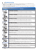
The snow melting control can operate either an electric or
a hydronic snow melting system. A hydronic system can be
further categorized as either boiler, mixing or pulse width
modulation zone operation, as well as, whether the boiler
plant is dedicated or non-dedicated for the snow melting
system. A dedicated boiler only provides heat from the snow
melting system. A non-dedicated boiler provides heat for
the snow melting system in addition to the space heating
and / or domestic hot water system. The control requires
that one of the following Application Modes is selected in
the System menu:
• PWM Pulse Width Modulation
• BOIL Boiler Operation
• MIX Mixing Operation
• ELEC Electrical Operation
• 090 Tandem Snow / Ice Detection using an
090 or 094
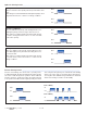
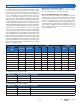
Electric Operation
The control operates the heat relay on a 20 minute pulse
width modulation cycle. The heat relay in turn activates a
line voltage electrical contactor to energize the electrical
cable heater installed in the slab. The heat relay on time is
determined by the calculated slab target and by the measured
slab temperature reading. As the slab temperature reaches
the slab target, the on time per cycle of the heat relay is
reduced to prevent the slab temperature from overshooting.
If no slab sensor is installed the heat relay remains on 100%
of the time until the Melt operation has completed. Idle and
Storm operation are not available when a slab sensor is not
installed. The electric operation requires the installation of
an outdoor sensor. A slab sensor is highly recommended in
order to reduce operating costs.
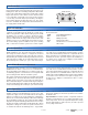
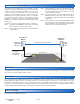
The Application Mode should be set to Pulse Width Modulation
(PWM) when the boiler or heat source is non-dedicated to
the snow melting system and there is no mixing system. The
snow melting system is considered to be a zone together with
space heating and the domestic hot water system.
The control operates the heat relay on a 20 minute pulse width
modulation cycle. The heat relay in turn activates the hydronic
heating system zone pump or zone valve. The heat relay on
time is determined by the calculated slab target and by the
measured slab temperature reading. As the slab temperature
reaches the slab target, the on time per cycle of the heat relay
is reduced to prevent the slab temperature from overshooting.
If no slab sensor is installed the heat relay remains on 100%
of the time until the Melt operation has completed. Idle and
Storm operation are not available when a slab sensor is not
installed. The hydronic PWM operation requires the installation
of an outdoor sensor and does not require a supply sensor.
A slab sensor is highly recommended in order to reduce
operating costs.
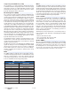
Boiler Operation
The Application Mode should be set to Boil when the snow
melting system has a dedicated boiler or heat source. This
requires the supply sensor to be installed. The boiler is piped
primary-secondary to the snow melting loop, allowing the
boiler to fire on and off while allowing continuous flow through
the snow melting system loop. The control calculates a Boiler
Target based upon the Slab Target which in turn is based upon
the measured outdoor temperature and the Melt, Idle or Storm
temperature setting. The control can operate a boiler in one
of six different methods: modulating boiler, 1 stage, EMS1,
EMS2, control and enable. The Boiler Target is shown in the
View menu. Settings for the boiler operation are located in
the Boiler menu.
Important Note: The boiler operator, or aquastat, remains in
the burner circuit and acts as a secondary upper limit on the
boiler temperature. The boiler aquastat temperature setting
must be adjusted above 200°F (93.5°C) in order to prevent
short cycling of the burner.