InstallationIOM-T-565 Manual Installation, Operation and Maintenance Thermostat 565 Wall Plate HVAC Interface Module Thermostat 565 Compatible With •C onventional systems: 2-stage heating, 2-stage cooling, fan and 2 accessories •H eat pump systems: 4-stage heating, 2-stage cooling, fan,reversing valve and 1 accessory • Supports dual fuel systems •A ccessory options: Humidifier, dehumidifier, HRV/ERV ventilator, heat pump loop valve ! WARNING Please read carefully before proceeding with installa
Table of Contents Important Safety Information . . . . . . . . . . . . . . . . . . . . . . . . . . . . . . . . . . . . . . . . . . . . . . . . . . . . . . 3 Installation . . . . . . . . . . . . . . . . . . . . . . . . . . . . . . . . . . . . . . . . . . . . . . . . . . . . . . . . . . . . . . . . . . . . 4 Preparation . . . . . . . . . . . . . . . . . . . . . . . .
Important Safety Information It is your responsibility to ensure that this thermostat is safely installed according to all applicable codes and standards. tekmar® is not responsible for damages resulting from improper installation and/or maintenance. This is a safety-alert symbol. The safety alert symbol is shown alone or used with a signal word (DANGER, WARNING, or CAUTION), a pictorial and/or a safety message to identify hazards.
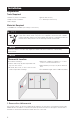
Installation Preparation Tools Required • tekmar or jeweler screwdriver • Drill (for wall anchor) • Phillips head screwdriver • 3⁄16" drill bit (for wall anchor) • Wire stripper Materials Required • 18 AWG LVT Solid Wire (low voltage connections) Ensure power to connecting equipment is off. To prevent the risk of personal injury and/or death, make sure power is not applied to the thermostat or HVAC Interface Module until they are fully installed and ready for configuration.
2. Mount thermostat base to wall Remove the back plate from the thermostat. 4. Attach the thermostat to back plate Align the 2 notches at the top of the base plate with the holes on the top of the thermostat then rotate on the hinge point down to close. Secure the thermostat back plate to a 2 x 4" electrical box with machine screws or to drywall using wood screws with wall anchors. 5.
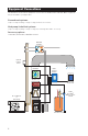
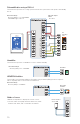
Equipment Connections This illustration shows various equipment connected to the HVAC Interface Module. Other equipment may be included in your application.
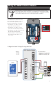
Wiring the HVAC Interface Module Ensure power to connecting equipment is off. To prevent the risk of personal injury and/or death, make sure power is not applied to the thermostat or HVAC Interface Module until they are fully installed and ready for configuration. All work must be done with power to the circuit being worked on turned off. The HVAC Interface Module includes three relay power jumper connectors. These are used to provide power between terminals when necessary.
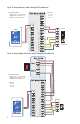
Up to 2-Stage Furnace and 2-Stage Air Conditioner Essential Settings: Heating Type = Conventional Equipment = 2 Heat/2 Cool Radiant Floor Heating = No Jumpers: J1 = On J2 = On J3 = On Furnace Air Conditioner Up to 2-Stage Hydronic Boiler and 2-Stage Air Conditioner Essential Settings: Heating Type = Conventional Equipment = 2 Heat/2 Cool Radiant Floor Heating = Yes Jumpers: J1 = On J2 = On J3 = Off 8
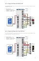
Up to 2-Stage Heat Pump with Auxiliary Heat The thermostat operates high cost electric resistance heat when the heat pump is unable to meet the building heating load.
Dehumidification using a DX Coil The thermostat operates the cooling system and runs the system fan at low speed to dehumidify the air. Essential Settings: Accessory Relay 1 or 2 = Dehumidifier Dehumidifier Type = DX Coil External Jumper Wires: R to Acc1 Air Handling Unit Humidifier The thermostat operates a humidifier to increase relative humidity.
Room Sensor When the location of the thermostat is not ideal for accurate temperature and humidity measurement, an optional room sensor can be installed in a better location. The 086 mounts flush to a wall, blending in with the room decor. tekmar Humidity & Temperature Sensor 086 •R emotely measure the temperature and relative humidity •T he Thermostat provides the option to disable the internal temperature and relative humidity sensor, and use the external sensor instead.
Home Screen After 60 seconds of inactivity, the thermostat home screen displays only the time and the temperature.
User Settings Away Use the Away setting to save energy when the building is unoccupied Home / Away Operates normally •T he Away temperature can be adjusted in the Setup / Temps menu. At Home Operates using the Away temperature selected in the Setup menu Away Info Save Schedule Early Start anticipates the time required to heat or cool a room and starts early. Go to the next group of program days. Schedule Current group of program days.
Display Setting TEMPERATURE UNITS Select °F or °C. ENERGY USE View the number of hours the heating or cooling has operated either daily or monthly. Range Default °F or °C °F 0 to 24 (daily) 0 to 744 (monthly) 0 hours Daily Usage Today Yesterday Tue Mon Sun Sat Fri 0 hrs 0 hrs 0 hrs 0 hrs 0 hrs 0 hrs 0 hrs 0 hrs 0 hrs 0 hrs 0 hrs 0 hrs 0 hrs 0 hrs View each day’s run time for both heating and cooling. Toggle between Daily and Monthly Usage.
Time TIME & DATE Aug 25 2019 1 30 PM OPTIONS The time and date can be manually set by highlighting a field and then using the or buttons. Choose from the time options listed below. Setting TIME FORMAT Select the time format. DAYLIGHT SAVING TIME Select if Daylight Savings Time is used in location. Range Default 12 or 24 hour 12 hour Off, On On Fan Fan On Auto Follow Schedule Fan The fan is normally off when set to auto but turns on when needed for the heating or cooling equipment.
Installer Settings Setup The Setup menu contains seven sub-menus that determine how the thermostat operates. The Access Level setting in the Toolbox menu determines how many settings are available to the user. SETUP MENU TOOLBOX TEMP SENSORS ALERTS RELAYS HUMIDITY Press back to return to the main Settings menu. VENT Setup - Toolbox Setting ERROR Displays any error messages. ACCESS LEVEL Select between user and installer access levels. User access level restricts access in the Setup Menu.
Setup - Temp Setting Range Default Screen Page 1 FLOOR MIN: Select the floor temperature minimum. Applies when there is both floor and an air sensors and when no schedule is set. HEAT TO AWAY Select the heating temperature when away. HEAT TO MIN LIMIT Off, 40 to 95°F Off, 4.5 to 35.0°C Off, 40 to 95°F 62°F Off, 4.5 to 35.0°C 16.5°C Off, 40 to 95°F Select the minimum heating temperature limit. HEAT TO MAX LIMIT Off, 4.5 to 35.0°C Off, 40 to 95°F Select the maximum heating temperature limit.
Setup - Sensors Setting SENSOR 1 Select the type of sensor connected to S1 and Com wiring terminals. SENSOR 2 Select the type of sensor connected to S2 and Com wiring terminals. SENSOR 3 Select the type of sensor connected to S3 and Com wiring terminals. INTERNAL ROOM SENSOR Select if the internal room temperature sensor is on or off. Only available when Sensor 1, 2 or 3 is set to read a room or floor sensor. INTERNAL HUMIDITY SENSOR Select if the internal humidity sensor is on or off.
Setup - Alerts Setting ROOM HOT WARNING Error on home screen if the room exceeds this temperature. ROOM COLD WARNING Error on home screen if the room falls below this temperature. Range Default Off, 40 to 100°F Off, 4.5 to 38.0°C Off Off, 40 to 100°F Off, 4.5 to 38.0°C Off Off, 5 to 95% Off Off, 5 to 95% Off Off, 1 to 24 hours Off Off, 200 to 2000 hours Off Off, 10,000 to 50,000 hours Off LOW HUMIDITY WARNING Error on home screen if the humidity falls below this threshold.
Setup - Relays (1 of 3) Setting HEATING TYPE Select between conventional heating or heat pump. Range Default Conventional, Heat Pump Conventional Conventional EQUIPMENT Select the number of stages of the heating and cooling equipment. RADIANT FLOOR HEATING Select if the first stage W1 heats a radiant floor. HEAT 1 DIFFERENTIAL Select when the first stage heating turns on. Turn on point is the Heat To setting minus the differential. HEAT 2 DIFFERENTIAL Select when the second stage heating turns on.
Setup - Relays (2 of 3) Setting Range Default 0 to 180 minutes 1 minute HEAT 4 DELAY Select the time delay when the fourth stage heating turns on. The time delay starts counting after the third stage heating is turned on. This setting is available when a heat pump is selected and there are at least 4 heating stages. COOL 1 DIFFERENTIAL Select when the first stage cooling turns on. Turn on point is the Cool To setting plus the differential.
Setup - Relays (3 of 3) Setting Range Default O (Orange), B (Blue) O HEAT PUMP REVERSING VALVE Select O for heat pumps designed for normally heating operation. Select B for heat pumps designed for normally cooling operation. This setting is only available for heat pump systems. G only, FAN RELAY Select which relays require fan operation. Combinations with W1 are not available when Radiant Floor Heating is set to yes.
Setup - Humidity Set the lowest relative humidity level. Range is 10 to 80% Default is 40% Available when Accessory 1 or 2 operates a humidifier. Humidity Humidify To: 40% Set the highest relative humidity level. Range is 20 to 90% Dehumidify To: 60% Default is 60% Available when Accessory 1 or 2 operates a dehumidifier.
Setup - HRV / ERV Ventilation VENTILATION FAN Wake Leave Return Sleep 30 min/hr VENTILATION Wake When a programmable schedule is used, there is a ventilation setting for each time period. 45 min/hr Auto 45 min/hr Auto On The ventilation fan runs for the set amount of time per hour.
Sequence of Operation Heating and Cooling Operation • The Heat On symbol is shown on the display when the thermostat is heating. • Heating for freeze protection is provided whenever the air or floor temperature falls below 40°F (4.5°C), regardless of operating mode. •T he Cool On symbol is shown on the display when the thermostat is cooling. The thermostat supports two heating system types: 1) conventional, or 2) heat pump.
When radiant floor heating is installed, it is always the first stage of heating, followed by the heat pump, and lastly any backup heating. This allows the floor to remain warm in the heating season.
Cooling Differentials The first and second stage cooling have adjustable differentials and time delay setting to determine when the stage turns on, and shut off when the room temperature reaches 0.5 and 0.0°F (0.25 and 0.0°C) above the Cool To setting respectively. Heat Pump Balance Point An air source heat pump’s Coefficient of Performance (COP) declines with falling outdoor air temperature.
Relative Humidity Operation Relative Humidity Sensor The thermostat includes an internal relative humidity (RH) sensor and has the option to connect to an external RH sensor. The installer has the option to disable the internal RH sensor when an external RH sensor is installed. When both the internal and external RH sensors are enabled, the RH reading is averaged. Humidifier Operation The thermostat controls the relative humidity (RH) by operating either the Accessory 1 or Accessory 2 relays.
Error Messages Description COMMUNICATION ERROR Communication between the display module and the HVAC Interface Module is interrupted. This error clears automatically once communication is re-established. This error can occur if the power supply voltage to the HVAC Interface Module is low. Check the voltage with a volt meter and that the transformer VA rating is enough to power all the equipment. MEMORY ERROR The thermostat memory settings are corrupted.
Description WATER LEAK DETECTOR WARNING A water leak has been detected and the water line has been shut off. The warning will automatically clear once the water leak detector has been reset. ROOM HOT WARNING The room temperature is above the Room Hot Warning setting in the Alerts menu. The warning will automatically clear once the room temperature falls below the setting. ROOM COLD WARNING The room temperature is below the Room Cold Warning setting in the Alerts menu.
Technical Data Thermostat 565 Literature ES-T-565, IOM-T-565, UserManual-T-565, JobRecord-T-565 Packaged weight 1.3 lb. (600 g) Dimensions Display: 41/2" H x 23/4" W x 9⁄16" D (114 x 70 x 14 mm) HVAC Interface Module: 7 7⁄16" H x 4 7⁄16" W x 11/4" D (188 x 112 x 31 mm) Display 3.
Limited Warranty and Product Return Procedure Limited Warranty The liability of tekmar under this warranty is limited. The Purchaser, by taking receipt of any tekmar product (“Product”), acknowledges the terms of the Limited Warranty in effect at the time of such Product sale and acknowledges that it has read and understands same.