
Submittal Sheet

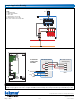

Sample Mechanical diagram
Sample Electrical diagram
561
_
C - 08/16 2 of 2 © 2016 tekmar
T: (250) 545-7749 • Fax: (250) 984-0815
tekmarControls.com
All speci cations are subject to change without notice.
Sample Application Drawing
This Submittal is not intended to provide full installation instructions and safety information. In order to avoid property
damage or injury, please refer to the complete installation manual and product safety information provided with the product.
WiFi Thermostat 561
C
R
RH1
W1
AWAY
S1
S2
SEN
COM
Zone Valve Control or
Switching Relay
C
R
AWAY
W
C
R
AWAY
RH1
W1
SEN
COM
S1
S2
Legend
P1 = Manifold Pump
T1 = WiFi Thermostat 561
V1 = Zone Valve
S1 = Optional Floor Sensor 079
S2 = Optional Indoor Sensor 084
ZVC1 = Zone Valve Control 304V, 306V
Install field
jumper wire
R to Rh1
ZVC1
S1
S2
P1
V1
ZVC1
T1
S1
S2