
Product Overview
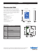

Sample Mechanical diagram
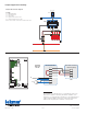
Sample Electrical diagram
ES-T-560
2145 2 of 2 © 2021 tekmar
Sample Application Drawing
Tel: 1-800-438-3903 • F: (250) 984-0815
watts.com/tekmar
The information contained herein is not intended to replace the
full product installation and safety information available or the
experience of a trained product installer. You are required to thor-
oughly read all installation instructions and product safety infor-
mation before beginning the installation of this product.
NOTICE
Thermostat 560
C
R
RH1
W1
AWAY
S1
S2
SEN
COM
Zone Valv
e Control or
Switching Relay
C
R
AWAY
W
C
R
AWAY
RH1
W1
SEN
COM
S1
S2
Legend
P1 = Manifold Pump
T1 = Thermostat 560
V1 = Zone Valve
S1 = Optional Floor Sensor 079
S2 = Optional Indoor Sensor 084
ZVC1 = Zone Valve Control 303V, 304V, 305V, 306V
Install field
jumper wire
R to Rh1
ZVC1
S1
S2
P1
V1
ZVC1
T1
S1
S2