557_D 11/12 tekmarNet® Thermostat 557 Zoning Replaces: 08/12 Installation & Operation Manual Introduction The tekmarNet® Thermostat 557 provides operation for: • One Stage Radiant Floor Heat, Two Stage Heat Pump for Heat & Cool, One Stage Backup Heat Or • Two Stage Heat, Two Stage Cool And includes • One Stage Fan Control • Humidity Control Energy Saving Features • • • • • • • • Programmable Schedule Zone Synchronization Zone Post Purge Warm Weather Shut Down Cooling Interlock Auto Heating Cycle Tempor
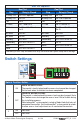
Table of Contents Getting Started ...............................2 Installation ...........................................3 Caution............................................3 Preparation .....................................3 Removing The Wiring Cover ...........3 Mounting The Thermostat...............4 Thermostat Wiring ..........................4 Compatible Sensors .......................5 Testing the Thermostat Wiring ........5 Switch Settings ....................................6 User Interface .....
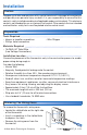
Installation Caution Improper installation and operation of this control could result in damage to the equipment and possibly even personal injury or death. It is your responsibility to ensure that this control is safely installed according to all applicable codes and standards. This electronic control is not intended for use as a primary limit control. Other controls that are intended and certified as safety limits must be placed into the control circuit.
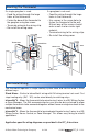
Mounting The Thermostat If a single gang box is used: • Feed the wiring through the large holes of the thermostat. • Fasten the base of the thermostat to the gang box using two screws. • Terminate wiring to the wiring strip. • Re-install the wiring cover. If a gang box is not used: • Feed the wiring through the large holes in the thermostat. • Use screws in the screw holes to fasten the thermostat to the wall. At least one of the screws should enter a wall stud or similar rigid material.
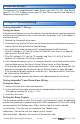
Compatible Sensors The thermostat is compatible with Indoor Sensor type 076, 077, 084, Slab Sensor type 072, 073, 079, Outdoor Sensor type 070, Duct Sensor type 083 and Humidity & Temperature Sensor type 086. Testing the Thermostat Wiring Testing tekmarNet ® 2 Wiring ---------------------------------------------------------------Testing the Power If the thermostat display turns on, this indicates that the thermostat is operating correctly and there are no electrical issues.
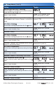
User Test Sequence Heat Test Step Cool Test Relay(s) Closed O Relay OFF Rc-O/B is opened Step O Relay ON Relay(s) Closed Rc-O/B B Relay ON Rc-O/B B Relay OFF Rc-O/B is opened Fan Rc-G Fan Rc-G Y1 Heat Rc-Y1 and Rc-G Y1 Cool Rc-Y1 and Rc-G Y2 Heat Rc-Y1 and Rc-Y2 and Rc-G Y2 Cool Rc-Y1 and Rc-Y2 and Rc-G W2 Heat Rh2-W2 W2 Cool Rh2-W2 W1 Heat Rh1-W1 Humidify* ACC-ACC Humidify* ACC-ACC Dehumidify* ACC-ACC or Rc-Y2 Dehumidify* ACC-ACC or Rc-Y2 HRV* Rc-Y2 HRV* Rc-Y2 Valve
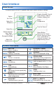
User Interface Home Screen The touchscreen of the 557 provides one touch access to these settings. Display Humidity, Heat & Cool settings, Floor or Outdoor temperature Adjust the Time Room Temperature Adjust the Schedule Turn the Fan on Away Key Switch between Auto, Heat, Cool, Off & Emergency Mode Adjust the Temperature Home Button Home Button. Return to the ‘Home’ Screen from any menu. Press and hold for 3 seconds to access the programming menus. Symbols Description HEAT ON Heat is turned on.
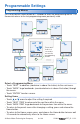
Programmable Settings Programming Menus Press and hold the Home button for 3 seconds to enter the programming menus. The thermostat returns to the last programming menu previously used. Press and hold for 3 seconds to access the programming menus. Select a Programming Menu ------------------------------------------------------------• Touch “NEXT” to advance (clockwise in above illustration) to the next menu. • Touch “BACK” to go backwards (counterclockwise in above illustration) through the menus.
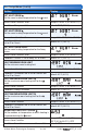
Set Temp Menu (1 of 4) Setting Display SET HEAT ROOM Set the room heating temperature for the Room event. Access Level: Installer, User Range: 40 to 95°F (4.5 to 35.0°C) Conditions: Always available Default: 70°F (21.0°C) SET HEAT ROOM Set the room heating temperature for the Room event. Access Level: Installer, User Conditions: Schedules are in use or Scenes are set to All or Guest. Range: 40 to 95°F (4.5 to 35.0°C) Default: 65°F (18.
Set Temp Menu (2 of 4) Setting Display WARM WEATHER SHUT DOWN Set the outdoor air temperature at which heating is suspended during the event. Range: CTRL (control), 40 to 100°F (4.5 to 38.0°C), OFF Access Level: Installer Conditions: An outdoor sensor must be available and Schedules are in use or Scenes is set to All or Default: CTRL Guest. SET COOL ROOM Set the room cooling temperature for the event. Access Level: Installer, User Range: 50 to 100°F (10.0 to 38.
Set Temp Menu (3 of 4) Setting Display COOL MAXIMUM ROOM LIMIT Set the maximum room cooling limit. Access Level: Installer Range: 50 to 100°F (10.0 to 38.0°C) Conditions: Always available Default: 100°F (38.0°C) FLOOR MINIMUM Set the floor heating temperature while in the event. Range: OFF, 40 to 122°F (4.5 to 50.0°C) Access Level: Installer, User Conditions: Sensor 1, 2 or 3 is set to Floor, and W1 Default: 72°F (22.0°C) Terminal is set to HRF1 or HRF2.
Set Temp Menu (4 of 4) Setting Display FAN Set the minimum percentage the fan should operate while in the event. This provides ventilation for the building. Each 10% is 6 minutes per hour. Access Level: Installer, User Conditions: Always available. 10 to 90% available when Ventilation Mode is On. FAN Set the minimum percentage the fan should operate while in the event or Away scene. This provides ventilation for the building. Each 10% is 6 minutes per hour.
Time Menu (2 of 2) Setting Display HOURS Select the current time hours. Access Level: Installer, User Range: 12 AM to 11 PM or 00 to 23 Conditions: Always available. Default: 12 AM DAY OF WEEK Select the current day of the week. Access Level: Installer, User Range: Sunday to Saturday Conditions: Always available. Default: Sunday MONTH Select the current month. Access Level: Installer, User Conditions: Always available.
Schedule Menu (1 of 2) The schedule menu can operate on a 24 hour or 7 day repeating schedule. When a 24 hour schedule is selected, “SuMoTuWeThFrSa” is shown on the top of the screen to show that the event time applies to all days of the week. When a 7 day schedule is selected, each individual day of the week is shown with the event time. Setting EVENT 1 The first programmable schedule time period of the day. The temperature settings are used during this time period.
Schedule Menu (2 of 2) Setting Display SCHEDULE Select if the thermostat should change the temperature automatically using a programmable schedule. OFF = Programmable schedule is not used. Zone = Applies to this thermostat only. Master 1, 2, 3, 4 = In charge of one of four available network schedules. Member 1, 2, 3, 4 = Follows selected network schedule.
Display Menu (2 of 2) Setting BACKLIGHT Select how the display backlight operates. ON = Always full brightness. DIM = Dim when inactive, on when touched. DIM = Dim in , off in . On when touched. ON = On in , off in . On when touched. OFF = Off when inactive, on when touched. Access Level: Installer, User Conditions: Always available. Display Range: DIM, ON, DIM , ON , OFF Default: DIM SECONDARY ITEM Determine the default item in the upper right hand corner of the Home screen.
Monitor Menu (1 of 5) Setting Display ROOM AVERAGE Current room temperature. Displays the average if there are multiple room sensors. Range: -58 to 212°F Access Level: Installer (-50.0 to 100.0°C) Conditions: Sensor 1, 2 or 3 is set to ROOM. Default: Not applicable. FLOOR AVERAGE Current floor temperature. Displays the average if there are multiple floor sensors. Access Level: Installer Conditions: Sensor 1, 2 or 3 is set to FLOR. Range: -58 to 212°F (-50.0 to 100.0°C) Default: Not applicable.
Monitor Menu (2 of 5) Setting Display SENSOR 2 The temperature measurement from the sensor 2 input wiring terminals. Access Level: Installer Range: -22 to 266°F (-30.0 to 130.0°C) Conditions: Setup menu setting Sensor 2 is set to ROOM, FLOR, or OUT. Default: Not applicable. SENSOR 3 The temperature measurement from the sensor 3 input wiring terminals. Access Level: Installer Range: -22 to 266°F (-30.0 to 130.0°C) Conditions: Setup menu setting Sensor 3 is set to ROOM, FLOR, or HUM.
Monitor Menu (3 of 5) Setting Display ROOM HIGH The highest recorded room temperature measurement. Touch the number and the ENTER key to reset. Range: -76 to 149°F (-60.0 to 65.0°C) Access Level: Installer, User Conditions: Setup setting Room Sensor is set to ON Default: Not applicable. or Sensor 1, 2 or 3 is set to ROOM. ROOM LOW The lowest recorded room temperature measurement. Touch the number and the ENTER key to reset. Range: -76 to 149°F (-60.0 to 65.
Monitor Menu (4 of 5) Setting HEAT Y2 HOURS The total number of hours the second stage of heat pump has been in heating operation. Touch the number and the ENTER key to reset. Access Level: Installer, User Conditions: Setup menu setting Y2 TYPE is set to HP2. HEAT W1 HOURS The total number of hours the W1 relay has been operated for heating. Touch the number and the ENTER key to reset. Access Level: Installer, User Conditions: Setup menu W1 TERM is set to HRF1, HRF2 or OTHR.
Monitor Menu (5 of 5) Setting Display COOL W2 HOURS The total number of hours the W2 relay has been operated for cooling. Touch the number and the ENTER key to reset. Access Level: Installer, User Range: 0000 to 9999 hours Conditions: Setup menu setting BACKUP W2 SOURC is set to TANK and BACKUP W2 TERM is set to Default: 0000 hours COIL. FAN HOURS The total number of hours the fan has been operated. Touch the number and the ENTER key to reset. Access Level: Installer, User Conditions: Always available.
Toolbox Menu (2 of 3) Setting STATUS INFO Displays the current status of the thermostat including any overrides from the tekmarNet® system control. Toggles between “Status Info” and the current status. Display System Normal = Thermostat operating normally. Override W1 = The tekmarNet® system control is either forcing the W1 relay on or off. Cooling Floor = Floor cooling is in effect. WWSD = Warm Weather Shut Down is in effect. CWSD = Cold Weather Shut Down is in effect.
Toolbox Menu (3 of 3) Setting Display DEVICE COUNT Provides a count of all the tekmarNet® thermostats and setpoint controls on the tekmarNet® system. Range: 1 to 24 Access Level: Installer Default: 1 Conditions: Must be connected to a tekmarNet® system. USER TEST Use the up or down arrow keys to select either the heat or cool test sequence, then press the NEXT key to begin. Press HOLD to pause at step for 5 minutes. Press NEXT to advance to the next step.
Setup Menu (1 of 7) Setting Display SENSOR 1 Select to the type of sensor connected to auxiliary sensor input 1. Range: OFF, ROOM, FLOR (floor), DUCT Default: OFF Access Level: Installer Conditions: Always available. SENSOR 2 Select to the type of sensor connected to auxiliary sensor input 2. Access Level: Installer Conditions: Always available. SENSOR 3 Select to the type of sensor connected to auxiliary sensor input 3.
Setup Menu (2 of 7) Setting Display W1 PUMP Select whether the primary or mix system pump on a tekmarNet® system control should operate while the first stage of heat W1 is operating. Access Level: Installer Range: OFF or ON ® Conditions: Only available when a tekmarNet system control is connected and the Setup menu setting W1 Default: ON TERM is set to HRF1, HRF2. W1 THERMAL MOTOR Select whether the first stage of heat W1 operates a thermally actuated zone valve (wax actuator).
Setup Menu (3 of 7) Setting Display BACKUP W2 THERMAL MOTOR Select whether the backup stage of heat W2 operates a thermally actuated zone valve (wax actuator). When set to ON, there is a 3 minute delay before operating the pump and any heat sources. Access Level: Installer Range: OFF or ON Conditions: BACKUP W2 TERMINAL is set to CONV Default: OFF or COIL. BACKUP W2 DELAY The minimum amount of time that the first stage W1 and the heat pump must be operating before the backup second stage W2 can turn on.
Setup Menu (4 of 7) Setting Y2 RELAY Select the equipment the Y2 relay operates. HP2 = Second stage heat pump AC2 = Second stage air conditioner HRV = Heat recovery ventilator DHUM = Dehumidifier VALV = Hydronic valve for building loop Display Range: OFF, HP2, AC2, HRV, DHUM, VALV Access Level: Installer Conditions: Always available. Default: OFF ACCESSORY RELAY Select the equipment the accessory relay operates.
Setup Menu (5 of 7) Setting Display Y2 DELAY Select the amount of time that must elapse after the Y1 relay is turned on before the Y2 relay is allowed. Access Level: Installer Range: AUTO, 5 to 180 minutes Conditions: Y2 RELAY is set to HP2 or AC2. Defaults: AUTO minutes COOLING CWSD Select the outdoor temperature below which the cooling system is disabled. Access Level: Installer Range: OFF, 35 to 75°F (OFF, 1.5 to 24.0°C) Conditions: Always available. Default: 55°F (13.
Setup Menu (6 of 7) Setting Display W1 HEAT WWSD Select the outdoor temperature above which the radiant floor heating is shut off. Range: OFF, 32 to 80°F (0 to 26.5°C) Access Level: Installer Conditions: W1 TERMINAL is set HRF1, HRF2, or OTHR and outdoor temperature is available. W CYCLES PER HOUR Select the number of heating cycles per hour. SYNC = 20 minute zone synchronization. AUTO = Automatic cycles per hour to minimize temperature swings.
Setup Menu (7 of 7) Setting Display AIR GROUP MASTER Select if the thermostat is a master of an air group. Access Level: Installer Range: NONE, 1 to 16 Conditions: The thermostat must be connected to Default: NONE other thermostats using tekmarNet®. PRIORITY Select either heating or cooling priority. Access Level: Installer Range: HEAT or COOL Conditions: Air Group Master is set to 1 to 16. VENTILATION MODE Select whether the fan provides ventilation.
Sequence of Operation Section A Heating Operation Set Heat Temperature -----------------------------------------------------------------------------The 557 can operate radiant floor heating, heat pump stage 1 and stage 2, and a backup heat source to provide heating in different combinations depending on the outdoor air temperature. The illustration below shows when each of the available heating units are available. The “Heat On” symbol is shown on the display when the thermostat is heating.
Warm Weather Shut Down-------------------------------------------------------------------When the outdoor air temperature exceeds the Warm Weather Shut Down (WWSD) setting on the tekmarNet® main control, the heating system is shut off. A W1 HEAT WWSD setting is available to allow the heat pump to heat the building while the radiant floor heat system is shut off during mild outdoor temperatures.
Cooling Mode - No Floor Sensor Room Warmer Set Heat Room Air & radiant floor cooling Y2 on Y1 on W1 cool on Y2 off Y1 off W1 cool off Air cooling No cooling allowed No heat pump Y2 on Y1 on Y2 off Y1 off Colder Outdoor Temperature Room Colder Warm Weather Shut Down Default = 70°F Cooling Cold Weather Shut Down Default = 60°F Balance Point Default = Off Cooling Mode - With Floor Sensor Room Warmer Set Heat Room Room Colder Air & radiant floor cooling Air cooling Radiant floor heating Floor minimu
Section D Hydronic Pump and Valve Operation Exercising ------------------------------------------------------------------------------------------------® When connected to a tekmarNet system control, the thermostat exercises the heat relay for 10 seconds every 3 days. Exercising helps prevent zone valves or zone pumps from failing due to precipitate buildup. During exercising, the thermostat shows “TEST” on the display.
Fan Post Purge -------------------------------------------------------------------------------------------The fan relay includes a post purge feature that operates the fan after the heating or cooling system has shut off. When a duct temperature sensor is installed the length of post purge is based on the air duct temperature and the Heatpurge or Coolpurge temperature settings.
The thermostat has up to five dehumidification modes. Operation Mode Required Relay(s) Sensor Required Stand Alone Dehumidifier Dehumidifier operates independently or the HVAC system. Available in all modes except off. DHM1 ACC RELAY None = DHUM or Y2 RELAY = DHUM Coil Dehumidification DHM2 A duct temperature sensor is required. A DX or chilled water coil is operated to maintain a discharge air temperature of 45°F (7°C). The room air temperature is allowed to fall up to 3°F (1.
Section G Air Group Operation In order to prevent heating and cooling at the same time, this thermostat can operate together with other thermostats on a tekmarNet® system to form an air group. On older model thermostats the air group functionality was previously described as a cool group. In an air group, one thermostat is assigned as the air group master. The air group master operates the cooling equipment for the group. This thermostat can be set to be a member of the air group.
Section I Temperature Adjustment Permanent Adjustment - No Schedule --------------------------------------------When no programmable schedule is used, touch the up or down arrows to permanently set the “Set Heat Room” or “Set Cool Room” temperature. This thermostat is capable of controlling both air and floor temperature.
Section J Programmable Schedules Energy savings can be achieved by lowering the heating temperature and increasing the cooling temperature when the building is unoccupied or during the night. When operating on a programmable schedule, a or a symbol is shown in the home menu. The or indicates the current operating temperature. All schedules are stored in permanent memory and are not affected by a loss of power.
Section K Scenes (System Override) Scenes provide an easy way to save energy while away on vacation, or override a programmable schedule when plans change. --------------------------------------------------------------Away Key -----------------------------------This thermostat includes an Away Key to quickly turn down the heating temperatures and increasing the cooling temperatures on all thermostats and suspend heating the domestic hot water tank to maximize energy savings.
Recommendation on How to Use Scenes -----------------------------------Choosing how to use scenes depends on the needs and lifestyle of the customer using the building. Multi-Tenant Apartments Scenes should be disabled (None) in multi-tenant buildings where each occupant has differing heating requirements. Residential Homes Some residential customers may not require scenes, in which case, scenes can be disabled (None).
Section M Access Levels The thermostat Toolbox menu supports four access levels: Installer (INST), User (USER), Limited (LTD), and Secure (SEC). The access level can be adjusted when the thermostat is unlocked. There are two locations to lock the thermostat: 1. Locally on the thermostat using the Lock switch located in the wiring area. 2.
Troubleshooting Error Messages (1 of 5) Error Message Description SETUP MENU SAVE ERROR The thermostat failed to read the Setup menu settings from memory and has reloaded the factory default settings. The thermostat stops normal operation until all settings in the Setup menu are checked except to provide freeze protection. To clear the error, set the access level to Installer and check all settings in the Setup menu.
Error Messages (2 of 5) Error Message Description DISPLAY MENU SAVE ERROR The thermostat failed to read the Display menu settings from memory and has reloaded the factory default settings. The thermostat continues to operate normally while displaying this error. To clear the error, set the access level to Installer and check all settings in the Display menu. tN2 PORT ERROR The thermostat has been connected to a tN2 zone already in use by a 2-stage zoning control.
Error Messages (3 of 5) Error Message Description ROOM SENSOR SHORT CIRCUIT ERROR Due to a short circuit, the thermostat is unable to read the built-in room temperature sensor. If Sensor 1, 2 or 3 is set to Room, or the thermostat is connected to a tekmarNet® system control, the thermostat continues to operate, otherwise operation stops. The error cannot be field repaired. Contact your tekmar® sales representative for repair procedures.
Error Messages (4 of 5) Error Message Description SYSTEM CONTROL LOST ERROR The thermostat can no longer communicate to the tekmarNet® system control. Check for open or short circuits in the tekmarNet® communication wiring. The error automatically clears once the tekmarNet® system control has been detected. If the tekmarNet® system control was intentionally removed from the system, remove and then re-apply power to the thermostat to clear the error.
Error Messages (5 of 5) Error Message Description ERROR AT THERMOSTAT There is an error on a different thermostat or setpoint control connected to the tekmarNet® system and not on this thermostat. 01 to 24 = Thermostat only network Go to the thermostat with the listed address to correct the error. ERROR AT THERMOSTAT There is an error on a different thermostat or setpoint control connected to the tekmarNet® system and not on this thermostat.
Limited Warranty and Product Return Procedure Limited Warranty The liability of tekmar under this warranty is limited. The Purchaser, by taking receipt of any tekmar product (“Product”), acknowledges the terms of the Limited Warranty in effect at the time of such Product sale and acknowledges that it has read and understands same.