554_D 02/15 tekmarNet® Thermostat 554 Zoning Replaces: New Installation & Operation Manual Introduction The tekmarNet® Thermostat 554 is a communicating touchscreen thermostat designed to operate one heating stage, one cooling stage, and a fan.
Table of Contents Important Safety Information ................................................................................3 Getting Started .....................................................................................................4 Installation .................................................................................................................4 Preparation ...........................................................................................................
Important Safety Information It is your responsibility to ensure that this thermostat is safely installed according to all applicable codes and standards. tekmar is not responsible for damages resulting from improper installation and/or maintenance. This is a safety-alert symbol. The safety alert symbol is shown alone or used with a signal word (DANGER, WARNING, or CAUTION), a pictorial and/or a safety message to identify hazards.
Getting Started Congratulations on the purchase of your new tekmar® thermostat. This manual will step through the complete installation, programming and sequence of operation for this control. At the back, there are tips for control and system troubleshooting.
To prevent the risk of personal injury and/or death, make sure power is not applied to the thermostat until it is fully installed and ready for final testing. All work must be done with power to the circuit being worked on turned off. Please be aware local codes may require this thermostat to be installed or connected by an electrician. Removing the Thermostat Base To remove the thermostat base: • Locate the tab on the bottom of the thermostat. • Push the tab with either your thumb or with a screwdriver.
If a gang box is not used: • Feed the wiring through the large hole in the thermostat base. • Mount the thermostat base directly to the wall. • Use screws in the screw holes to fasten the thermostat to the wall. At least one of the screws should enter a wall stud or similar rigid material. • Terminate wiring to the wiring strip. • Push the thermostat front onto the thermostat base. Thermostat Front Thermostat Base Stud Wall Do not over-tighten wiring screws. Hand-tighten only.
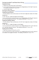
Only qualified personnel should perform testing procedures. A licensed electrician is recommended. Testing the Thermostat Wiring Testing tekmarNet ® 2 Wiring -----------------------------------------Testing the Power If the thermostat display turns on, this indicates that the thermostat is operating correctly and there are no electrical issues. In the event that the display is off, or the display is cycling on and off: 1. Remove the thermostat wiring cover. 2.
Testing tekmarNet ® 4 and Stand Alone Wiring -------------------------Testing the Power 1. Remove the front cover from the thermostat. 2. Use an electrical test meter to measure (ac) voltage between the R and C terminals. The reading should be 24 V (ac) ±10%. 3. Install the front cover. Testing the Relay Outputs -------------------------------------------Testing the Heat W Relay 1. Set the Mode to Heat and increase the Set Heat temperature above the Room temperature. 2.
Mounting the Thermostat Push the thermostat front onto the thermostat base. Installation is now complete. Thermostat Base Thermostat Front Push Lock Switch Settings Back of Thermostat Mmm YYYY Lot # 12345 1 2 Unlock Unused Switch Settings / tekmarNet Thermostat 554 ON One Stage Heat, One Stage Cool, One Fan www.tekmarcontrols.com Power: tN2 or 24 V (ac) ±10% 1.
User Interface Home Screen Display Heat & Cool settings, Floor or Outdoor temperature Adjust the Time Adjust the Schedule Room Temperature Away Key Turn the Fan on Switch between Auto, Heat, Cool & Off Mode Adjust the Temperature Home Button Return to the ‘Home’ Screen from any menu Symbols Description HEAT ON Heat is turned on. ARROWS Adjust the displayed setting. COOL ON Cooling is turned on. SCENE AWAY Operating at Away temperature. FAN The fan is turned on.
Programmable Settings Programming Menus Press and hold the Home button for 3 seconds to enter the programming menus. The thermostat returns to the last programming menu previously used. Press and hold for 3 seconds to access the programming menus. Select a Programming Menu ----------------------------------------• Touch “NEXT” to advance (clockwise in above illustration) to the next menu. • Touch “BACK” to go backwards (counterclockwise in above illustration) through the menus.
Set Temp Menu (1 of 4) Setting Display SET HEAT ROOM Set the room heating temperature for the Room event. Access Level: Installer, User Range: 40 to 95°F (4.5 to 35.0°C) Conditions: Always available. Default: 70°F (21.0°C) SET HEAT ROOM Set the room heating temperature for the Room event. Access Level: Installer, User Conditions: Schedules are in use or Scenes are set to All or Guest. Range: 40 to 95°F (4.5 to 35.0°C) Default: 65°F (18.
Set Temp Menu (2 of 4) Setting Display WARM WEATHER SHUT DOWN Set the outdoor air temperature at which heating is suspended during the event. Range: CTRL (control), 40 to 100°F (4.5 to 38.0°C), OFF Access Level: Installer Conditions: An outdoor sensor must be available and Default: CTRL (with tN System Schedules are in use or Scenes is set to All or Guest. Control or 60°F (15.5°C) (Standalone) SET COOL ROOM Set the room cooling temperature for the event.
Set Temp Menu (3 of 4) Setting Display COOL MAXIMUM ROOM LIMIT Set the maximum room cooling limit. Access Level: Installer Range: 50 to 100°F (10.0 to 38.0°C) Conditions: Always available. Default: 100°F (38.0°C) FLOOR MINIMUM Set the floor heating temperature while in the event. Access Level: Installer Range: OFF, 40 to 122°F (4.5 to 50.0°C) Conditions: Sensor 1 or 2 is set to Floor, and W Terminal is set to HRF1, HRF2 or OTHR. Default: 72°F (22.
Set Temp Menu (4 of 4) Setting Display FAN Set the minimum percentage of time the fan should operate while in the event. This provides ventilation for the building. Each 10% is 6 minutes per hour. Access Level: Installer, User Conditions: 10 to 90% available if Ventilation Mode is On. FAN Set the minimum percentage of time the fan should operate while in the event or Away scene. This provides ventilation for the building. Each 10% is 6 minutes per hour.
Time Menu (1 of 1) Setting Display MINUTES Select the current time minutes. Access Level: Installer, User Range: 00 to 59 Conditions: Always available. Default: 00 HOURS Select the current time hours. Access Level: Installer, User Range: 12 AM to 11 PM or 00 to 23 Conditions: Always available. Default: 12 AM DAY OF WEEK Select the current day of the week. Access Level: Installer, User Range: Sunday to Saturday Conditions: Always available. Default: Sunday MONTH Select the current month.
Schedule Menu (1 of 2) The schedule menu can operate on a 24-hour or 7-day repeating schedule. When a 24-hour schedule is selected, “SuMoTuWeThFrSa” is shown on the top of the screen to show that the event time applies to all days of the week. When a 7-day schedule is selected, each individual day of the week is shown with the event time. Setting EVENT 1 The first programmable schedule time period of the day. The temperature settings are used during this time period.
Schedule Menu (2 of 2) Setting Display SCHEDULE Select if the thermostat should change the temperature automatically using a programmable schedule. OFF = Programmable schedule is not used. Zone = Applies to this thermostat only. Master 1, 2, 3, 4 = In charge of one of four available network schedules. Member 1, 2, 3, 4 = Follows selected network schedule.
Display Menu (1 of 1) Setting Display UNITS Select Fahrenheit or Celsius as the temperature units. Access Level: Installer, User Conditions: Always available. BACKLIGHT Select how the display backlight operates. DIM = Dim when inactive, on when touched. ON = Always full brightness. DIM = Dim in , off in . On when touched. ON = On in , off in . On when touched. OFF = Off when inactive, on when touched. Access Level: Installer, User Conditions: Always available.
Scenes Menu (1 of 1) Setting Display SCENES Enable or disable the use of scenes (building overrides) on this thermostat. Access Level: Installer, User Range: NONE, AWAY, ALL, GUEST Conditions: Settings ALL and GUEST only available Default: NONE in Installer access level. SCENE 4 Select how the thermostat should respond to scene 4. Access Level: Installer Conditions: Scenes is set to All. AWAY KEY Enable or disable the away touch key on the home screen.
Monitor Menu (1 of 3) Setting Display ROOM AVERAGE Current room temperature. Displays the average if there are multiple room sensors. Range: -58 to 212°F Access Level: Installer (-50.0 to 100.0°C) Conditions: Sensor 1 or 2 is set to ROOM. Default: Not applicable. FLOOR AVERAGE Current floor temperature. Displays the average if there are multiple floor sensors. Access Level: Installer Conditions: Sensor 1 or 2 is set to FLOR.
Monitor Menu (2 of 3) Setting Display SENSOR 2 The temperature measurement from the sensor 2 input wiring terminals. Range: -58 to 212°F (-50.0 to 100.0°C) Access Level: Installer Conditions: Sensor 2 is set to ROOM, FLOR, or OUT. Default: Not applicable. OUTDOOR HIGH The highest recorded outdoor air temperature measurement. Touch the number and the ENTER key to reset. Access Level: Installer, User Range: -76 to 149°F (-60.0 to 65.0°C) Conditions: An outdoor temperature is available.
Monitor Menu (3 of 3) Setting Display FLOOR LOW The lowest recorded floor temperature measurement. Touch the number and the ENTER key to reset. Range: -76 to 149°F Access Level: Installer, User (-60.0 to 65.0°C) Conditions: Sensor 1 or 2 is set to FLOR. Default: Not applicable. FILTER HOURS The total number of hours the fan has been operating since the air filter was last replaced. Touch the number and the ENTER key to reset and clear the Change Filter warning message.
Toolbox Menu (1 of 2) Setting ACCESS LEVEL Selects the access level of the thermostat, which determines which menus and items are available. Access Level: Installer (INST), User, Limited (LTD), Secure (SEC) Conditions: Adjustable only when thermostat switch setting set to UNLOCK OR tekmarNet® system control switch setting set to UNLOCK. STATUS INFO Toggles between “Status Info” and the current status including any overrides from the tekmarNet® system control.
Toolbox Menu (2 of 2) Setting Display ADDRESS The tekmarNet® address of this thermostat. To manually set the address, use the up or down arrow buttons. Range: AUTO, 01 to 24, Access Level: Installer b:01 to b:24, 1:01 to 1:24, 2:01 to 2:24, 3:01 to 3:24 Conditions: tekmarNet ®2 or 4 detected. Default: AUTO SOFTWARE AND TYPE VERSION Displays the software version and the tekmar type number. Access Level: Installer, User, Limited, Secure Range: 554 Conditions: Always available.
Setup Menu (1 of 4) Setting Display SENSOR 1 Select the auxiliary sensor input 1 type. Range: OFF, ROOM, FLOR (floor), COIL, DUCT Access Level: Installer Conditions: Coil sensor option available when W TERMINAL is set to COIL. Duct sensor option available when W TERMINAL is Default: OFF set to FURN or COIL. Floor sensor option not available when W TERMINAL is set to FURN or COIL. SENSOR 2 Select the auxiliary sensor input 2 type.
Setup Menu (2 of 4) Setting Display W THERMAL MOTOR Select whether the first stage of heat W operates a thermally actuated zone valve (wax actuator). When set to ON, there is a 3-minute delay before operating the pump and any heat sources. Access Level: Installer Range: OFF or ON Conditions: Available when a tekmarNet® system control is connected and W TERMINAL is set to HRF1, HRF2, Default: OFF CONV or COIL. Also available when connected to a tN2 Wiring Center and W TERMINAL set to OTHR.
Setup Menu (3 of 4) Setting Display BASELOAD Select the level of radiant floor baseload heating. This warms the floor so that solar gain and/or air heating systems do not cause cold floors. Access Level: Installer Range: OFF, LOW, MED, HIGH ® Conditions: Only available when a tekmarNet system control is connected and W TERMINAL is Default: OFF set to HRF1 or HRF2 and SENSOR 1 or 2 is not set to FLOR (floor). AIR GROUP MASTER Select if the thermostat is a master of an air group.
Setup Menu (4 of 4) Setting Display FAN DELAY Select the time delay to allow the fan coil or furnace to warm up prior to activating the fan. This avoids blowing cold air. Range: NONE, 0:10 to 6:00 minutes Access Level: Installer Conditions: Sensor 1 is not set to COIL and W Default: 0:30 minutes TERMINAL is set to COIL or FURN. HEAT COIL MINIMUM Select the minimum coil temperature before operating the fan for heating. Range: OFF, 70 to 180°F (OFF, 21.0 to 82.
Sequence of Operation Heating Operation Set Heat Temperature -----------------------------------------------When using only a room temperature sensor, the thermostat operates the heating system to maintain the Set Heat Room temperature. The “Heat On” symbol is shown on the display when the thermostat is heating. Floor Heating-------------------------------------------------------When using both a room and a floor temperature sensor, the floor is heated at least to the Floor Minimum setting.
Cooling Operation Set Cool Temperature ----------------------------------------------The thermostat operates an air conditioner to provide cooling. The “Cool On” symbol is shown on the display when the thermostat is cooling. Cooling Cold Weather Shut Down------------------------------------When the outdoor air temperature falls below the Cooling Cold Weather Shut Down (CWSD) setting on the thermostat, the cooling system is shut off.
Hydronic System Supply Pump --------------------------------------When connected to a tekmarNet® system control, the thermostat’s W Pump setting affects the operation of the primary pump or mix pump on the system control. When the thermostat is connected to the boiler bus, the boiler system or primary pump is operated. When the thermostat is connected to the mix bus, the mix system pump is operated. If the thermostat operates a motorized or thermal motor zone valve, the W Pump setting should be set to On.
Air Group Operation To prevent heating and cooling at the same time, this thermostat can operate with other thermostats on a tekmarNet system to form an air group. The 554 can be set up as the air group master. Other heat-only thermostats can be set up as an air group member. When operating as an air group, the air temperature readings of all the air group member thermostats are communicated to the air group master thermostat and an average air temperature is determined.
Temperature Adjustment Permanent Adjustment ― No Schedule -----------------------------------When no programmable schedule is used, touch the up or down arrows to permanently set the “Set Heat Room” or “Set Cool Room” temperature. This thermostat is capable of controlling both air and floor temperature.
Programmable Schedules Energy savings can be achieved by lowering the heating temperature and increasing the cooling temperature, for example, at night, or at other times when the building is unoccupied. When operating on a programmable schedule, a or a symbol is shown in the Home menu. The or indicates the current operating temperature. All schedules are stored in permanent memory and are not affected by a loss of power.
Scenes (System Override) Scenes provide an easy way to save energy, when building residents are on vacation, for example, or override a programmable schedule when plans change. Away Key ------------------------------------------------------------------This thermostat includes an Away Key to set the thermostat to quickly turn down the heating temperatures and increase the cooling temperatures on all thermostats and suspend heating the domestic hot water tank to maximize energy savings.
Recommendation on How to Use Scenes ----------------------------Deciding how to use scenes depends on the needs and lifestyle of the customer using the building. Multi-Tenant Apartments Scenes should be disabled (None) in multi-tenant buildings where each occupant has differing heating requirements. Residential Homes Some residential customers may not require scenes. In that case, scenes can be disabled (None).
Access Levels The thermostat Toolbox menu supports four access levels: Installer (INST), User (USER), Limited (LTD), and Secure (SEC). The access level can be adjusted when the thermostat is unlocked. There are two locations to lock the thermostat: 1. Locally on the thermostat using the Lock switch located in the wiring area. 2.
Troubleshooting Error Messages (1 of 4) Error Message Description SETUP MENU SAVE ERROR The thermostat failed to read the Setup menu settings from memory and has reloaded the factory default settings. The thermostat stops normal operation until all settings in the Setup menu are checked except to provide freeze protection. To clear the error, set the access level to Installer and check all settings in the Setup menu.
Error Messages (2 of 4) Error Message Description DISPLAY MENU SAVE ERROR The thermostat failed to read the Display menu settings from memory and has reloaded the factory default settings. The thermostat continues to operate normally while displaying this error. To clear the error, set the access level to Installer and check all settings in the Display menu. tN2 PORT ERROR The thermostat has been connected to a tN2 zone already in use by a 2-stage thermostat.
Error Messages (3 of 4) Error Message Description ROOM SENSOR OPEN CIRCUIT ERROR Due to an open circuit, the thermostat is unable to read the built-in room temperature sensor. If Sensor 1 or 2 is set to Room, or the thermostat is connected to a tekmarNet® system control, the thermostat continues to operate; otherwise operation stops. The error cannot be field repaired. Contact your tekmar® sales representative for repair procedures.
Error Messages (4 of 4) Error Message Description SCHEDULE MASTER ERROR Two thermostats on the tekmarNet ® system have been set to the same Schedule Master number. The thermostat operates at the temperature settings while this error is present. To clear the error, select a different Schedule Master number, set a different Schedule Member number, set the Schedule to Zone, or set the Schedule to None. SCHEDULE MEMBER ERROR The thermostat can not longer detect its schedule master.
Technical Data ® tekmarNet Thermostat 554; One Stage Heat, One Stage Cool, One Fan Literature 554_A, 554_C, 554_D, 554_J, 554_Q, 554_U Control Microprocessor control. This is not a safety (limit) control. Packaged weight 0.8 lb. (350 g) Dimensions 5" H x 3-1/4" W x 15/16" D (127 x 82 x 23 mm) Enclosure White PVC plastic, NEMA Type 1 Approvals Meets Class B: ICES & FCC Part 15 Ambient conditions Indoor use only, 32 to 122°F (0 to 50°C), RH ≤90% non-condensing Power supply 24 V ±10%, 60 Hz, 1.
Limited Warranty and Product Return Procedure Limited Warranty The liability of tekmar under this warranty is limited. The Purchaser, by taking receipt of any tekmar product (“Product”), acknowledges the terms of the Limited Warranty in effect at the time of such Product sale and acknowledges that it has read and understands same.