
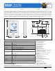
Submittal
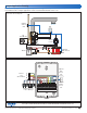

Below is a sample application drawing for this product. This application may include other tekmar products that are required
for installation. More sample applications can be found at www.tekmarControls.com.
Sample Application Drawing
Sample Mechanical diagram
Product design, software and literature are Copyright ©2013 by
tekmar Control Systems Ltd.,
A Watts Water Technologies Company
2 of 2
All specifications are subject to change without notice.
Printed in Canada. 553_C - 04/13.
tekmar Control Systems Ltd., A Watts Water Technologies Company.
Head Offi ce: 5100 Silver Star Road,
Vernon, B.C. Canada V1B 3K4, 250-545-7749, Fax. 250-545-0650 Web Site: www.tekmarControls.com
Sample Electrical diagram
W
R
Y
G
Optional
Outdoor
Sensor
070
Optional
Slab
Sensor
079
Furnace
and
Air Conditioner
tN4 Wiring Center
or Zone Manager
tN4 C W
R
C
tN2
tN4
tN2
R
Rh W Rc Y G/O S1 S2
ACC Com
No Power
ACC
Y
G
W
Outdoor
Sensor
070
553
Air
Conditioner
Furnace and Fan
Boiler
Wiring
Center
Optional
Slab Sensor
079