
Submittal

Below is a sample application drawing for this product. This application may include other tekmar products that are required
for installation. More sample applications can be found at www.tekmarcontrols.com.
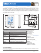
Sample Application Drawing
Sample Electrical diagram
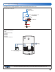
Sample Mechanical diagram
Product design, software and literature are Copyright © 2011 by:
tekmar Control Systems Ltd. and tekmar Control Systems, Inc.
2 of 2
All specifications are subject to change without notice.
Printed in Canada. C 552 - 07/11.
tekmar Control Systems Ltd., Canada, tekmar Control Systems, Inc., U.S.A.
Head Offi ce: 5100 Silver Star Road,
Vernon, B.C. Canada V1B 3K4, 250-545-7749, Fax. 250-545-0650 Web Site: www.tekmarcontrols.com
Legend
P1 = Zone Manifold Pump
Z1 = Zone 1
Z2 = Zone 2
Z3 = Zone 3
Z4 = Zone 4
S1 = Optional Slab Sensor
313
tN2 tN2
C
tN2
tN4
tN2
R
Rh W1
No Power
S1 S2
Com
House Control, Wiring Center
or Zone Manager
P1
4 Zone Manifold
Z1
S1
Z3
Z2 Z4
House Control, Wiring Center
or Zone Manager
S1
tekmarNet
®
Thermostat 552