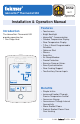
D552 08/11 tekmarNet® Thermostat 552 Zoning Replaces: New Installation & Operation Manual Features Introduction ® The tekmarNet Thermostat 552 provides operation for: • One Stage Heat • • • • • • • • • • • • • • • Touchscreen Bright Backlight tekmarNet® Communication Outdoor Temperature Display Floor Temperature Display 7-Day, 4 Event Programmable Schedule Optimum Start Scenes Away Key Air Group Member Freeze Protection Exercise Pump or Valves Zone Synchronization Floor Cooling Support Two Auxiliary S
Table of Contents Getting Started ..............................2 Installation .........................................2 Caution ..........................................2 Preparation ....................................3 Removing The Thermostat Base...3 Mounting The Thermostat Base ....4 Thermostat Wiring .........................4 Testing the Thermostat Wiring ......6 Mounting the Thermostat ..............8 Cleaning the Thermostat ...............8 Switch Settings ..................................
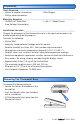
Preparation ------------------------------------------------------------------------------------Tools Required ----• tekmar or jeweller screwdriver • Wire Stripper • Phillips head screwdriver Materials Required -----------------------------------------------------------------------------------• 18 AWG LVT Solid Wire • 2, #6 x 1” Wood Screws (Low Voltage Connections) Installation Location ------------------------------------------------------------------------------Choose the placement of the thermostats ear
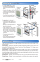
Mounting The Thermostat Base If a single gang box is used: • Feed the wiring through the large hole of the thermostat base. • Fasten the base of the thermostat to the gang box. • Terminate wiring to the wiring strip. • Push the thermostat front onto the thermostat base. If a gang box is not used: • Feed the wiring through the large hole in the thermostat base. • Mount the thermostat base directly to the wall. • Use screws in the screw holes to fasten the thermostat to the wall.
Wiring - tekmarNet®2 --------------------------------------------------------------------------------- Optional Sensor 1 No Power tN4 C R tN2 tN2 Rh W1 tN2 tN2 Optional Sensor 2 S1 Com S2 tN2 Wiring Center tN2 House Control tN2 Zone Manager Wiring - tekmarNet ® 4---------------------------------------------------------------------------------- Install field jumper wire R to Rh No Power tN4 C R tN2 tN2 Rh W1 tN4 C R Optional Sensor 1 Optional Sensor 2 S1 Com S2 W tN4 Wiring Center tN4 Zone
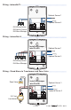
Wiring - Stand Alone to Switching Relay or Zone Valve Control ------------ Install field jumper wire R to Rh W R W R W R (T) (T) (T) (T) (T) (T) 24 V Com No Power tN4 C R tN2 tN2 Rh W1 Optional Sensor 1 Optional Sensor 2 S1 Com S2 Switching Relay X X Zone 1 Zone 2 Zone 3 H N H N H N Zone Pump N L N L Compatible Sensors The thermostat is compatible with Indoor Sensor type 076, 077, 084, Floor Sensor type 072, 073, 079, and Outdoor Sensor type 070.
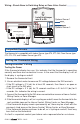
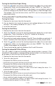
Testing the Heat Zone Output Wiring 1. Touch the button and set the heating temperature above the current room temperature. Make sure the display does not show “WWSD” or “Floor Max”. 2. When the “Heat On” symbol appears on the display, use an electrical meter to check for voltage on the House Control, Wiring Center, or Zone Manager relay. The voltage is 24 V (ac) for zone valves, and 120 V (ac) for zone pumps when operating correctly.
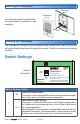
Mounting the Thermostat Thermostat Base Thermostat Front Push the thermostat front onto the thermostat base. Installation is now complete. Push Cleaning the Thermostat The thermostats’s exterior can be cleaned using a damp cloth. Moisten the cloth with water and wring out prior to wiping the control. Do not use solvents or cleaning solutions.
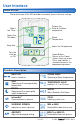
User Interface Home Screen The touchscreen of the 552 provides one touch access to these settings. Display the Floor or Outdoor temperature. Adjust the Time. Adjust the Schedule. Room Temperature. Away Key. Adjust the Temperature. Turn the Heat on or Off. Home Button. Return to the ‘Home’ Screen from any menu. Press and hold for 3 seconds to access the programming menus. Home Button Symbols Description HEAT ON Heat is turned on. SCENE AWAY Operating at Away temperature.
Programmable Settings Programming Menus Press and hold the Home button for 3 seconds to enter the programming menus. The thermostat returns to the last programming menu previously used. Press and hold for 3 seconds to access the programming menus. Select a Programming Menu ------------------------------------------------------------• Touch “NEXT” to advance (clockwise in above illustration) to the next menu. • Touch “BACK” to go backwards (counterclockwise in above illustration) through the menus.
Set Temp Menu (1 of 3) Setting Display SET HEAT ROOM Set the room heating temperature during the event. Access Level: Installer, User Room Range: 40 to 95°F (4.5 to 35.0°C) Conditions: Room Sensor set to ON or Sensor 1 or Default: 70°F (21.0°C) Sensor 2 set to Room. SET HEAT ROOM Set the room heating temperature during the event. Access Level: Installer, User Room Range: 40 to 95°F (4.5 to 35.
Set Temp Menu (2 of 3) Setting Display SET HEAT FLOOR Set the floor heating temperature while in the event. Floor Access Level: Installer, User Range: 40 to 122°F (4.5 to 50.0°C) Conditions: Room Sensor set to OFF and Sensor 1 or Sensor 2 set to Floor, and Schedules are in use or Scenes are set to All or Guest. Default: 65°F (18.5°C) WARM WEATHER SHUT DOWN Set the outdoor air temperature at which heating is suspended during the event. Access Level: Installer Range: CTRL (control), 40 to 100°F (4.
Set Temp Menu (3 of 3) Setting FLOOR MAXIMUM Set the floor maximum temperature in order to protect the floor covering. Suggested settings: Tile = 90°F (32°C) Hardwood Floor = 85°F (29°C) Display Range: 40 to 122°F (4.5 to 50.0°C), OFF Access Level: Installer Conditions: Sensor 1 or Sensor 2 set to Floor, and either Room Sensor set to ON, or Room Sensor Default: 85°F (29.5°C) set to OFF while Sensor 1 or 2 is set to Room, and Schedules or Scenes are in use.
Time Menu (2 of 2) Setting Display MONTH Select the current month. Access Level: Installer, User Range: JANUARY to DECEMBER Conditions: Schedule is used or Clock is set to ON. Default: JANUARY DAY OF MONTH Select the day of the current month. Access Level: Installer, User Conditions: Schedule is used or Clock is set to ON. Range: 1 to 31 Default: 1 YEAR Select the current year. Access Level: Installer, User Range: 2011 to 2255 Conditions: Schedule is used or Clock is set to ON.
Schedule Menu (1 of 2) The schedule menu can operate on a 24 hour or 7 day repeating schedule. When a 24 hour schedule is selected, “SuMoTuWeThFrSa” is shown on the top of the screen to show that the event time applies to all days of the week. When a 7 day schedule is selected, each individual day of the week is shown with the event time. Setting Display EVENT 1 The first programmable schedule time period of the day. The temperature settings are used during this time period.
Schedule Menu (2 of 2) Setting Display SCHEDULE Select if the thermostat should change the temperature automatically using a programmable schedule. OFF = Programmable schedule is not used. Zone = Applies to this thermostat only. Master 1, 2, 3, 4 = In charge of one of four available network schedules. Member 1, 2, 3, 4 = Follows selected network schedule.
Display Menu (2 of 2) Setting Display BACKLIGHT Select how the display backlight operates. ON = Always full brightness. DIM = Dim when inactive, on when touched. DIM = Dim in , off in . On when touched. ON = On in , off in . On when touched. OFF = Always off. Access Level: Installer, User Range: DIM, ON, DIM , ON , OFF Conditions: Always available. Default: DIM SECONDARY ITEM Determine the default item in the upper right hand corner of the display.
Monitor Menu (1 of 3) Setting Display ROOM AVERAGE Current room temperature. Displays the average if there are multiple room sensors. Range: -58 to 212°F (-50.0 to Access Level: Installer 100.0°C) Conditions: Sensor 1 or 2 is set to Room. Default: Not applicable. FLOOR AVERAGE Current floor temperature. Displays the average if there are multiple floor sensors. Access Level: Installer Conditions: Sensor 1 or 2 is set to Floor. Range: -58 to 212°F (-50.0 to 100.0°C) Default: Not applicable.
Monitor Menu (2 of 3) Setting OUTDOOR HIGH The highest recorded outdoor air temperature measurement. Touch the number and touch the ENTER key to reset. Display Range: -76 to 149°F (-60.0 to 65.0°C) Access Level: Installer, User Conditions: Setup menu setting SENSOR 1 is set to Outdoor or an outdoor temperature is available on Default: Not applicable. the tekmarNet® System. OUTDOOR LOW The lowest recorded outdoor air temperature measurement. Touch the number and touch the ENTER key to reset.
Monitor Menu (3 of 3) Setting Display FLOOR LOW The lowest recorded floor temperature measurement. Touch the number and touch the ENTER key to reset. Range: -76 to 149°F (-60.0 to Access Level: Installer, User 65.0°C) Conditions: Setup menu setting SENSOR 1 or 2 is Default: Not applicable. set to FLOR. HEAT W1 The total number of hours the W1 relay has been operated for heating. Touch the number and touch the ENTER key to reset.
Toolbox Menu (2 of 3) Setting Display WWSD = Warm Weather Shut Down is in effect. Air Group Master Cool = Heating is off while the cooling system is on. Optimum Start = Heating is started early in order to meet temperature setpoint at Event 1 or Event 3. Floor Max = The floor has reached its maximum temperature. Some under heating could occur. Floor Min = The floor is operating at its minimum temperature. Some over heating could occur.
Toolbox Menu (3 of 3) Setting DEVICE COUNT Provides a count of all the tekmarNet® thermostats and setpoint controls on the tekmarNet® system. Access Level: Installer Conditions: Must be connected to a tekmarNet® system. USER TEST Select to begin the test routine by touching the up arrow. Step 1: The W1 relay will turn on. Touch Cancel to stop test routine. Touch Hold to pause test routine at current step for 5 minutes. Access Level: Installer Conditions: Always available.
Setup Menu (1 of 2) Setting Display SENSOR 1 Select to the type of sensor connected to auxiliary sensor input 1. Access Level: Installer Range: OFF, ROOM, FLOR (floor), OUT (outdoor) Conditions: Always available. Default: OFF SENSOR 2 Select to the type of sensor connected to auxiliary sensor input 2. Access Level: Installer Range: OFF, ROOM, FLOR (floor) Conditions: Always available. Default: OFF ROOM SENSOR Select whether the built-in room temperature sensor is on or off.
Setup Menu (2 of 2) Setting W1 THERMAL MOTOR Select whether the first stage of heat W1 operates a thermally actuated zone valve (wax actuator). When set to ON, there is a 3 minute delay before operating the pump and any heat sources. Access Level: Installer Conditions: Setup menu setting W1 TERM is set to CTRL, HRF1, HRF2, CONV, or COIL. W CYCLES PER HOUR Select the number of heating cycles per hour. SYNC = Synchronize thermostats to a 20 minute cycle.
Sequence of Operation Section A Heating Operation Set Heat Temperature -----------------------------------------------------------------------------When using only a room temperature sensor, the thermostat operates the heating system to maintain the Set Heat Room temperature. When using only a floor temperature sensor, the thermostat operates the heating system to maintain the Set Heat Floor temperature. In this case, the thermostat does not try to control the air temperature.
Freeze Protection ----------------------------------------------------------------------------------The thermostat operates the heat whenever the room or floor temperature falls below 40°F (4.5°C) even when the mode is set to off. Exercising ------------------------------------------------------------------------------------------------When connected to a tekmarNet® system control, the thermostat exercises the heat relay for 10 seconds every 3 days.
Section C Air Group Operation In order to prevent heating and cooling at the same time, this thermostat can operate together with other thermostats on a tekmarNet® system to form an air group. On older model thermostats the air group functionality was previously described as a cool group. In an air group, one thermostat is assigned as the air group master. The air group master operates the cooling equipment for the group. This thermostat can be set to be a member of the air group.
Section E Temperature Adjustment Permanent Adjustment - No Schedule --------------------------------------------When no programmable schedule is used, touch the up or down arrows to permanently set the “Set Heat” temperature. This thermostat is capable of controlling the air or floor temperature. When set to control the floor temperature alone, the display will show “Floor” instead of “Room”.
Section F Programmable Schedules Lowering the room temperature setting reduces the amount of fuel required to heat the building resulting in energy savings. When operating on a programmable schedule, a or a symbol is shown in the home menu. The or indicates the current operating temperature. All schedules are stored in permanent memory and are not affected by a loss of power.
Section G Scenes (System Override) Scenes provide an easy way to save energy while away on vacation, or override a programmable schedule when plans change. --------------------------------------------------------------Away Key -----------------------------------This thermostat includes an Away Key to quickly turn down the heating temperature on all thermostats and suspend heating the domestic hot water tank to maximize energy savings. To turn on the Away Key, go to the Scene menu.
Recommendation on How to Use Scenes -----------------------------------Choosing how to use scenes depends on the needs and lifestyle of the customer using the building. Multi-Tenant Apartments Scenes should be disabled (None) in multi-tenant buildings where the each occupant has differing heating requirements. Residential Homes Some residential customers may not require scenes, in which case, scenes can be disabled (None).
Section I Access Levels The thermostat Toolbox menu supports four access levels: Installer (INST), User (USER), Limited (LTD), and Secure (SEC). The access level can be adjusted when the thermostat is unlocked.
Troubleshooting Error Messages (1 of 5) Error Message Description SETUP MENU SAVE ERROR The thermostat failed to read the Setup menu settings from memory and has reloaded the factory default settings. The thermostat stops normal operation until all settings in the Setup menu are checked except to provide freeze protection. To clear the error, set the access level to Installer and check all settings in the Setup menu.
Error Messages (2 of 5) Error Message Description SCENES MENU SAVE ERROR The thermostat failed to read the Scenes menu settings from memory and has reloaded the factory default settings. The thermostat continues to operate normally while displaying this error. To clear the error, set the access level to Installer and check all settings in the Scenes menu. DISPLAY MENU SAVE ERROR The thermostat failed to read the Display menu settings from memory and has reloaded the factory default settings.
Error Messages (3 of 5) Error Message Description ROOM SENSOR SHORT CIRCUIT ERROR Due to a short circuit, the thermostat is unable to read the built-in room temperature sensor. If Sensor 1 or 2 is set to Room, or the thermostat is connected to a tekmarNet® system control, the thermostat continues to operate, otherwise operation stops. The error cannot be field repaired. Contact your tekmar® sales representative for repair procedures.
Error Messages (4 of 5) Error Message Description SENSOR 2 OPEN CIRCUIT ERROR Due to an open circuit, the thermostat is unable to read auxiliary Sensor 2. The thermostat stops normal operation if Sensor 2 is the only active Room or Floor sensor or if a Floor Maximum temperature has been set. Check the auxiliary sensor wire for short circuits according to the sensor installation manual. It may be necessary to replace the auxiliary sensor.
Error Messages (5 of 5) Error Message Description ERROR AT THERMOSTAT There is an error on a different thermostat or setpoint control connected to the tekmarNet® system and not on this thermostat. 01 to 24 = There is an error on a thermostat or setpoint control with this tekmarNet® address. ERROR AT THERMOSTAT There is an error on a different thermostat or setpoint control connected to the tekmarNet® system and not on this thermostat.
Frequently Asked Questions Symptom Look for... Corrective Action indicates heat relay W1 is on. If the is displayed and there is no heat, check if the zone valve or zone pump is operating. No heat MODE The thermostat is in the Off mode. Touch the mode key to change to Heat. No or keys Touch the ‘Cancel Away’ key on the display.
Job Record Job site Location ________________________________________________ Thermostat Location _____________________________________________ Setup menu Setting Setup menu Setting Sensor 1 W Cycles / Hour Sensor 2 Baseload Room Sensor Floor W1 Terminal Air Group Member W1 Pump Technical Data tekmarNet® Thermostat 552; One Stage Heat Packaged weight 0.8 lb.
Limited Warranty and Product Return Procedure Limited Warranty The liability of tekmar under this warranty is limited. The Purchaser, by taking receipt of any tekmar product (“Product”), acknowledges the terms of the Limited Warranty in effect at the time of such Product sale and acknowledges that it has read and understands same.