
Wiring Guide


9 of 12 © 2008 W 444 - 12/08
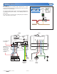
System Pump Red wire or Terminal 4
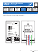
The module includes two different methods to turn on a
system pump.
1. Powered output on back of module.
•
• Connect 120 V (ac) to the black wire.
•
• Connect the mix system pump to the red wire.
•
• Connect the ground to the green wire.
•
• Connect the neutral wire to the mix system pump.
•
• Ensure that a wire nut is installed on the blue wire (if not
used).
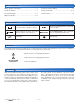
24 V (ac) Power Terminals 2,3
Wire 24 V (ac) to terminals R and C.
If a Zone Manager is used:
•
• Connect C on the 444 to C on the Zone Manager.
•
• Connect R on the 444 to R on the Zone Manager.
Black
Red
Blue
Green
Pump
120 V (ac)
Neutral
System
Pump
Ground
L
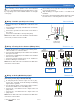
If a 24 V (ac) transformer is used:
•
• Connect C on the 444 to C on the transformer.
•
• Connect R on the 444 to R on the transformer.
23
CR
Power
Transformer
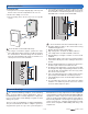
Mix Supply Sensor (tekmar 082) Terminals 8, 9
•
• Ensure the Mix Supply Sensor is either tie strapped to
the pipe or placed in a 1/2” OD immersion well.
•
• The sensor should be located on the supply pipe between
the heating system and the mixing device.
•
• Connect the two wires from the Mix Supply Sensor to
the Com and Mix (8 and 9) terminals.
89
Com Mix
-
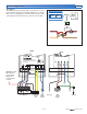
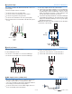
2. 24 V (ac) output on the front of the module.
•
• Connect the Sys Pmp terminal 4 to a Zone Manager
335 or 336 Pmp A input (terminal 3). Then wire the mix
system pump to the Zone Manager 335 zone group
pump A (terminals 30 and 31) or Zone Manager 336
zone group pump A (terminals 22 and 23).
•
• Connect the Sys Pmp terminal 4 to a Dual Zone Manager
337 Pmp B input (terminal 3). Then wire the mix system
pump to the Dual Zone Manager 337 zone group pump
B (terminals 29 and 31).
Note: Ensure that a wire nut is installed on the Red wire
on the back of the module.
23
CR
Power
tN4 C Pmp tN1 C R
Zn Grp A
123456
Zone Manager
Pump
tN4 C Pmp
Zn Grp A A
123
Zn Grp
PmpA
N
4
Sys
Pmp
Zone
Manager
System
Pump