
Wiring Guide


© 2008 W 444 - 12/08 8 of 12
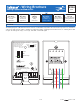
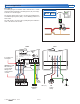
•
• Connect 120 V (ac) to the Black wire on the back of the
module.
•
• Connect the injection pump to the Blue wire on the back
of the module.
•
• Connect the ground to the Green wire on the back of
the control.
•
• Connect the neutral wire to the injection pump.
Note: Ensure that a wire nut is installed on the Red wire
(if not used) on the back of the module.
Wiring a Variable Speed Injection Pump Back of Module
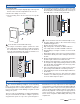
Wiring the Module Terminals 1-9
The following section explains how to wire individual
devices to the Mixing Expansion Module 444. For step
by step wiring refer to the terminal number on the right
of the page.
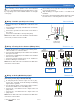
Wiring a Floating Action Actuator (Mixing Valve) Terminals 2, 5, 6
•
• Identify the direction of rotation for the mixing valve,
either clockwise or counterclockwise.
•
• Connect Open (terminal 5) to the actuator motor terminal
that opens the valve.
•
• Connect Close (terminal 6) to the actuator motor terminal
that closes the valve.
•
• Connect C from the actuator motor to a C terminal on
the Zone Manager or transformer.
Note: Ensure that a wire nut is installed on the Blue wire
on the back of the module.
Wiring an Analog Modulating Signal Terminals 7, 8
(0-10 V (dc), 2-10 V (dc), 0-20 mA, 4-20 mA)
•
• A 3rd party device that accepts a 0-10 V (dc),
2-10 V (dc), 0-20 mA, 4-20 mA analog modulating
signal can be operated.
•
• For mA analog signals, cut the jumper wire located in
the lower left hand corner of the wiring area.
•
• Connect the + on terminal 7 to the + input on the 3rd
party device.
•
• Connect the – on terminal 8 to the – input on the 3rd
party device.
Note: Ensure that a wire nut is installed on the Blue wire
on the back of the module.
Pump
120 V (ac)
Neutral
Variable Speed
Injection Pump
Ground
L
Black
Red
Blue
Green
Analog Input on
Actuator or VFD
78
Mod Com
+–
+–
•
• Before wiring ensure all power is turned off and take all
necessary precautions.
•
• Strip all wiring to a length of 3/8 in. or 10 mm for all
terminals.
•
• Refer to the current and voltage ratings at the back of this
brochure before connecting devices to this control.
Actuating Motor
C
OR
Clockwise
to Open
Counterclockwise
to Open
C
Zone
Manager or
Transformer
Actuating Motor
56
RR
Opn Cls
56
RR
Opn Cls
C C
Zone
Manager or
Transformer