
Wiring Guide


3 of 12 © 2008 W 444 - 12/08
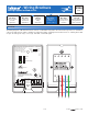
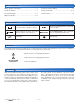
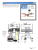
Electrical Drawings
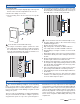
Module Installation
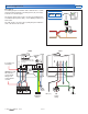
The electrical drawing examples on the following
pages show the 444 in common applications. Choose
the drawing that most accurately depicts the components
in your system and use that drawing as a guide to aid in
wiring your system.
These are only concept drawings, not engineered drawings.
They are not intended to describe a complete system nor
any particular system. It is up to the system designer to
determine the necessary components for and configuration
of the particular system being designed including additional
equipment, isolation relays (for loads greater than the
controls specified output ratings) and any safety devices
which in the judgment of the designer are appropriate in
order to properly size, configure and design that system
and to ensure compliance with building and safety code
requirements.
To Install the 444:
1. Grasp the front cover by the fingertip grips on the top and
bottom of the enclosure and pull the front cover off.
2. Remove the wiring cover screw.
3. The mounting holes in the enclosure accept #6
screws.
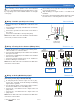
4. The module can be installed two ways:
•
• On a larger electrical box (Figure 1) where the extra
low voltage (ELV) wiring enters the module from inside
the electrical box. The ELV wiring must be rated at
least 300 V and minimum 194°F (90°C) and have over
current protection to 10 A maximum.
Figure 1
Figure 2
•
• On a smaller electrical box (Figure 2) where the extra
low voltage (ELV) wiring enters the module from outside
the electrical box. The ELV wiring must be used only on
CEC/NEC Class 2 circuits per the CEC/NEC.
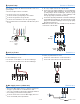
5. The electrical box must have a minimum depth of 1.75”
.
•
• Rough-in wiring is made to the electrical box using
standard wiring practices.
•
• All wires must be rated at least 300 V.
•
• High voltage wires should be 14 AWG conductors.
•
• Low voltage wires should be 18 AWG conductors.
•
• Strip all wiring to a length of 3/8 inch or 10 mm for all
terminals.
•
• High voltage wiring connections are made inside the
electrical box directly to the wires exiting the back of the
module.
•
• All unused high voltage wires located on the back of the
module require a wire nut to insulate the wire.
•
• An approved circuit breaker or power disconnect that
de-energizes the high voltage wiring should be located
near the module, and marked as the 120 V (ac) power
disconnect for this module.
•
• 120 V (ac) high voltage power supply circuits must be
protected by 15 A maximum overcurrent protection.
•
• Only qualified personnel should attempt installation of
the module.
6. To reassemble the enclosure, first replace the wiring
chamber cover and then push the front cover onto the
enclosure until it snaps into place.