
Wiring Guide


© 2008 W 444 - 12/08 2 of 12
Table of Contents
Wiring Symbols & Definitions ........................................2
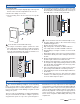
Module Installation .........................................................3
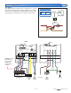
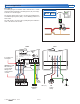
Electrical Drawings ......................................................3-7
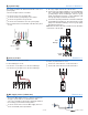
Wiring the Module .......................................................8-9
Troubleshooting the Wiring ..........................................10
Testing the Module .................................................. 10-11
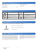
Technical Data ..............................................................12
Defi nitions
The following defined terms and symbols are used throughout this manual to bring attention to the presence of hazards of
various risk levels, or to important information concerning the life of the product.
– Caution: Refer to accompanying documents
– Caution: Refer to accompanying documents
INSTALLATION
CATEGORY II
– Local level appliances
Improper installation and operation of this control could
result in damage to the equipment and possibly even
personal injury or death. It is your responsibility to ensure
that this control is safely installed according to all applicable
codes and standards. This electronic control is not intended
for uses as a primary limit control. Other controls that are
intended and certified as safety limits must be placed into
the control circuit. Do not attempt to service the control.
Refer to qualified personnel for servicing. Apart from any
field replaceable fuse(s) there are no user serviceable
parts. Attempting to do so voids warranty and could result
in damage to the equipment and possibly even personal
injury or death.
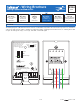
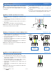
Wiring Symbols
Caution
Dry contact switch. Operates a device.
Black reverse lettering denotes an internally
powered output.
Powered switch. 24-115 V (ac) power,
switched output to valve, pump, etc.
Do not apply power to these terminals.
Serious control damage will result.
tekmarNet
®
4
Earth ground