
Wiring Guide


11 of 12 © 2008 W 444 - 12/08
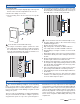
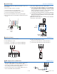
Testing the System Pump Terminals 2, 4
The System Pump LED is green when the Pump contact
is energized.
If using the output on the back of the module:
•
• Use a voltmeter to check for 120 V (ac) +/- 10% between
the Red wire and neutral.
If using the 24 V (ac) output on the front of the module:
•
• Use a voltmeter to check for 24 V (ac) +/- 10% between
the Sys Pmp and the C terminals.
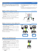
Testing tekmar Sensors Terminals 8, 9
To test the sensors, the actual temperature at each sensor
location must be measured.
•
• Use a good quality digital thermometer with a surface
temperature probe for ease of use and accuracy. Where
a digital thermometer is not available, strap a spare
sensor alongside the one to be tested and compare the
readings.
•
• Disconnect each sensor from the control.
•
• Test the sensors resistance according to the instructions
in the sensor Data Brochure D 070.
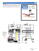
Testing the Variable Speed Injection Pump Back of Module
•
• Press the Test button on the tN4 System Control.
•
• Once the Mix % Output reaches 100%, press the Test
button once again to pause the control at this output.
•
• Measure the voltage on the variable speed injection
pump. The reading should be 120 V (ac) +/- 10%.
•
• Press the Test button to resume the test sequence.
Note: At outputs below 100%, the electrical meter will not
read correctly.
If power is not present:
•
• Measure the voltage on the Black wire and the neutral.
The reading should be 120 V (ac) +/- 10%.
•
• If voltage is present on the Black wire but not on the Blue
wire, and the Mix % Output is 100%, then the internal
overload protection rated at 2.5 A may be damaged and
require repair. Contact your tekmar sales representative
for details on the repair procedures if this circuit is
damaged.
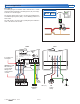
Testing the Floating Action Terminals 2, 5, 6
•
• Press the Test button on the tN4 System Control.
•
• When the Mix % Out is increasing, use an electrical
test meter to measure the (ac) voltage between the
C terminal 2 and Opn (Open) terminal 5. The reading
should be 24 V (ac) +/– 10%.
•
• When the Mix % Out is decreasing, use an electrical
test meter to measure the (ac) voltage between the
C terminal 2 and Cls (Close) terminal 6. The reading
should be 24 V (ac) +/– 10%.
Testing the Analog V (dc) Signal Terminals 7, 8
•
• Press the Test button on the tN4 System Control.
•
• Once the Mix % Output reaches 100%, press the Test
button once again to pause the control at this output.
•
• Set the multimeter to measure V (dc).
•
• Connect the multimeter probes to the analog modulating
output terminals (7 and 8).
•
• The reading should be near 10 V (dc).
Testing the Analog mA Signal Terminals 7, 8
•
• Press the Test button on the tN4 System Control.
•
• Once the Mix % Output reaches 100%, press the Test
button once again to pause the control at this output.
•
• Remove the wires from the analog modulating output
terminals (7 and 8).
•
• Set the multimeter to measure mA.
•
• Connect the multimeter probes to the analog modulating
output terminals (7 and 8).
•
• The reading should be near 20 mA.
•
• Replace wires.