
Wiring Guide


© 2008 W 444 - 12/08 10 of 12
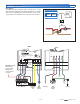
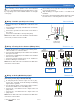
Testing the Power Terminals 2, 3
Testing the tN4 Communication Terminals 1, 2
The tN4 Bus LED is green when the 444 detects
communication. If the tN4 Bus LED is off, ensure that
the tN4 and C wires are properly terminated on the 444
and at the device on the other end of the wires. The tN4
and C wires are polarity sensitive.
To check the tN4 and C wires, disconnect the wires on
one end and connect them together using a wire nut. Then
measure the other end of the wires using the continuity
check on a digital multimeter.
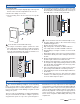
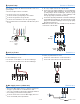
Testing the Module
Troubleshooting the Wiring
23
CR
Power
Test Meter
###
Control Terminals
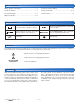
The following tests are to be performed using standard
testing practices and procedures and should only be carried
out by properly trained and experienced persons.
A good quality electrical test meter, capable of reading from
at least 0-300 V (ac), 0-30 V (dc), 0-2,000,000 Ohms, and
testing for continuity is essential to properly test the wiring
and sensors.
For an explanation on the use of the Test Button, the “Test”
sequence or any error messages, refer to the Data Brochure
of the tN4 System Control.
General
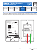
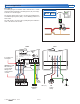
tN4 Communication Terminals 1, 2
Wire the tN4 communication to terminals tN4 and C on the
desired tN4 mix temperature bus.
If a Zone Manager is used:
•
• Connect tN4 terminal 1 on the 444 to tN4 on the Zone
Manager.
•
• Connect C terminal 2 on the 444 to C on the Zone
Manager.
If a Zone Manager is not used:
•
• Connect tN4 on the 444 to tN4 on another tN4 device
on the same mix tN4 bus.
•
• Connect C on the 444 to C on another tN4 device on
the same mix tN4 bus.
The Power LED is green when 24 V (ac) is applied to the
C and the R terminals. Use a voltmeter to check for 24 V
(ac) +/- 10% on terminals C and R.
12
tN4 C
tN4 C
Zn Grp A
12
Zone Manager
444