
Wiring Guide


3 of 8 © 2008 W 441 - 12/08
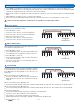
Type Coupler Arrow Color
710, 711, 712, 713, 714 White
720, 721, 722, 723, 724 Red
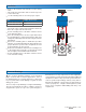
Installation
•
• Remove the manual valve handle from the mixing
valve.
•
• Thread the two anti-rotation bolts to the two top holes
on the valve body.
•
• Use the following chart to select the proper coupler:
•
• The arrow on the coupler points towards the valve body.
Place the coupler onto the valve shaft.
•
• Set the actuating motor’s automatic / manual selector
to the manual setting.
•
• Place the actuating motor onto the coupler. Ensure that
the actuating motor’s rotation range matches that of the
mixing valve. Manually rotate the valve using the actuator
hand wheel.
•
• Ensure the actuating motor’s hand wheel position
indicator (clear plastic film with red stripe) indicates the
proper direction to open the valve. If required, the clear
position indicator can be reversed.
•
• Remove the hand wheel and fasten the actuating motor
to the mixing valve using the screw under the hand
wheel. Replace the hand wheel when finished.
•
• Set the actuating motor’s automatic / manual selector
to the automatic setting.
Actuating
Motor
Hand Wheel
Coupler
Anti-Rotation
Bolts
Valve
Electrical Drawings
The electrical drawing examples on the following
pages show the 441 in common applications. Choose
the drawing that most accurately depicts the components
in your system and use that drawing as a guide to aid in
wiring your system.
These are only concept drawings, not engineered drawings.
They are not intended to describe a complete system nor
any particular system. It is up to the system designer to
determine the necessary components for and configuration
of the particular system being designed including additional
equipment isolation relays (for loads greater than the
controls specified output ratings) and any safety devices
which in the judgment of the designer are appropriate in
order to properly size, configure and design that system
and to ensure compliance with building and safety code
requirements.