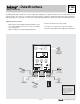
- Data Brochure D 356 09/08 Mixing Control 356 The Mixing Control 356 is designed to control the supply water temperature to a hydronic system in order to provide outdoor reset or setpoint operation. The control uses a variable speed injection pump to regulate the supply water temperature, while protecting the boiler against flue gas condensation. The control has a Liquid Crystal Display (LCD) to view system status and operating information.
How To Use The Data Brochure This brochure is organized into four main sections. They are: 1) Sequence of Operation, 2) Installation, 3) Control Settings, and 4) Troubleshooting. The Sequence of Operation section has three sub-sections. We recommend reading Section A: General Operation of the Sequence of Operation, as this contains important information on the overall operation of the control. Then read the sub-sections that apply to your installation.
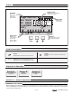
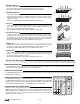
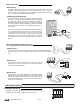
Display Number Field Displays the current value of the selected item Item Field Displays an abbreviated name of the selected item OUTDR DSGN DIFF BOIL TARGET MIX MIN MAX ROOM WWSD INDR VIEW ADJUST °F °C Terminal Unit 10 30 50 70 90 % Out Return Supply Status Field Displays the current menu Mixing Demand { Displays the current status of the control’s inputs, outputs and operation Menu Field Buttons Selects Menus, Items and adjusts settings Item Symbol Description Pointer Displays the control op
OPERATION Design Supply The 356 uses a variable speed injection pump to control the supply water temperature to a hydronic system. The supply water temperature is based on either the current outdoor temperature, or a fixed setpoint. Increasing Water Temperature Terminal Unit Outdoor Reset When the outdoor design (OUTDR DSGN) setting is not set to OFF, the 356 calculates a mixing supply temperature based on the current outdoor air temperature and the Characterized Heating Curve settings.
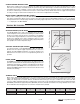
CHARACTERIZED HEATING CURVE When used as a mixing reset control, the 356 varies the supply water temperature based on the outdoor air temperature. The control takes into account the type of terminal unit that the system is using. Since different types of terminal units transfer heat to a space using different proportions of radiation, convection and conduction, the supply water temperature must be controlled differently.
High Mass Radiant (1) This type of a hydronic radiant floor is embedded in either a thick concrete or gypsum pour. This heating system has a large thermal mass and is slow acting. Default values: MIX DSGN = 120°F (49°C), MIX MAX = 140°F (60°C) Low Mass Radiant (2) This type of radiant heating system is either attached to the bottom of a wood sub-floor, suspended in the joist space, or sandwiched between the sub-floor and the surface.
Section C: Boiler Operation Section C1 General Operation Section C2 Boiler Sensor Placement Section C1: General Operation BOILER OPERATION When the 356 determines that boiler operation is required, the Boiler contact terminals (5 and 6) close. While the Boiler contact is closed, the burner segment in the LCD is displayed. BOILER MINIMUM (BOIL MIN) Most boilers require a minimum water temperature in order to prevent flue gas condensation.
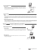
Installation CAUTION Improper installation and operation of this control could result in damage to the equipment and possibly even personal injury. It is your responsibility to ensure that this control is safely installed according to all applicable codes and standards. This electronic control is not intended for use as a primary limit control. Other controls that are intended and certified as safety limits must be placed into the control circuit.
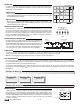
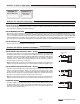
V Ω V Test The Powered Inputs Mixing Demand Measure the voltage between the mixing demand wire and the power wire that goes to R+ of the control. The voltmeter should read between 22 and 26 V (ac) when the mixing demand device calls for heat. Mixing demand switch Class II Transformer C R 24 V (ac) Test The Outputs Boiler Make sure power to the boiler circuit is off and short the boiler wires. When the boiler circuit is powered up, the boiler should fire.
Output Connections Boiler Contact 5 6 Boiler The Boiler terminals (5 and 6) are an isolated output in the 356. There is no power available on these terminals from the control. These terminals are to be used as a switch to either make or break the boiler circuit. When the 356 requires the boiler to fire, it closes the contact between terminals 5 and 6.
Quick Setup The quick setup can be used for both outdoor reset and setpoint operation. To enter the installer programming mode, set the Advanced / Installer DIP switch to Installer. OUTDOOR RESET Access the ADJUST menu by pressing and holding simultaneously for 1 second, the Item, The display will now show the word ADJUST in the top right corner. ADJUST °F The ROOM adjustment is the first item displayed. Use the or ROOM setting is set to the desired room air temperature. and buttons (all three buttons).
Se ct i In on st a Ad ller va nc ed View Menu (1 of 1) Display OUTDR Description Range VIEW °F Current outdoor air temperature as measured by the outdoor sensor. This is also the default display for the control. (OUTDR DSGN ≠ OFF) -67 to 149°F (-55 to 65°C) B3 Current mixed supply water temperature as measured by the mixing sensor. 14 to 266°F (-10 to 130°C) B1 B2 B3 Target mixed supply is the temperature the control is currently trying to maintain at the mixing sensor.
Se ct i In on st a Ad ller va nc ed Adjust Menu (2 of 2) Display ADJUST °F MAX MIX Description Range B3 The maximum supply temperature for the mixing system. (OUTDR DSGN ≠ OFF) 80 to 225°F (27 to 107°C) C2 The location of the boiler sensor. This effects operation of the boiler contact. (Boiler sensor is present) Return, Supply C1 The minimum temperature allowed for the boiler target temperature.
Testing the Control The Mixing Control 356 has a built-in test routine which is used to test the main control functions. The 356 continually monitors the sensors and displays an error message whenever a fault is found. See the following pages for a list of the 356’s error messages and possible causes. Quick Test Press and hold the button, the Boiler relay closes and the variiable speed injection pump turns on to 100% of its output speed.
Error Messages VIEW The control was unable to read a piece of information from its EEPROM. This error can be caused by a noisy power source. The control will load the factory defaults and stop operation until all the settings are verified. OUTDR VIEW The control is no longer able to read the outdoor sensor due to a short circuit. In this case the control assumes an outdoor temperature of 32°F (0°C) and continues operation. Locate and repair the problem as described in the Data Brochure D 070.
Technical Data Mixing Control 356 Variable Speed Literature Control Packaged weight Dimensions Approvals Ambient conditions Power supply Var. Pump Relays Mixing demand Sensors included Optional devices — — — — — — — — — — — D 356, A 356’s, D 001, D 070, E 021. Microprocessor PID control; This is not a safety (limit) control. 1.5 lb. (670 g), Enclosure C, white PVC plastic 4-3/4” H x 2-7/8” W x 7/8” D (120 x 74 x 22 mm) CSA C US, CSA 22.2 No 24 and UL 873, meets class B: ICES & FCC Part 15.