
Application Brochure


Product design, software and literature are Copyright © 2000 by:
tekmar Control Systems Ltd. and tekmar Control Systems, Inc.
tekmar Control Systems Ltd., Canada
tekmar Control Systems, Inc., U.S.A.
Head Office: 5100 Silver Star Road
Vernon, B.C. Canada V1B 3K4
Tel. (250) 545-7749 Fax. (250) 545-0650
Web Site: www.tekmarcontrols.com
Control Systems
System Operation
All specifications are subject to change without notice.
12 of 12
A 356-6 05/00
Product design, software and literature are Copyright © 2000 by:
tekmar Control Systems Ltd. and tekmar Control Systems, Inc.
Printed in Canada. A 356-6 05/00.
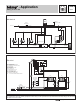
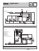
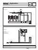
The Mixing Control 356 and the Boiler Control 256 are combined to provide full outdoor reset to two (or more) mixed zones and partial
outdoor reset to two (or more) boiler zones. The output of the variable speed injection pump is modulated to provide a mixed supply
water temperature to the mixed zones, and protect the boiler from flue gas condensation. The boiler operates at the required temperature
in order to satisfy all the loads. The supply of heat to an indirect Domestic Hot Water (DHW) tank is controlled through an external relay.
Heat Source Details The heat source can be either a high mass or low mass non-condensing boiler.
Piping Details Thermostat controlled zone valves are piped into the mixed loop. The variable speed injection pump (P3) is piped in
primary / secondary in order to isolate the boiler loop flow rate from the mixed loop flow rate. Thermostat controlled zone valves are
piped into the boiler loop. Heat is supplied to the DHW tank through a DHW pump (P2). The boiler pump (P1) provides flow through the
boiler, and boiler zones, and ensures flow past the variable speed injection pump take-off. A balancing valve (V2) creates a pressure
differential so that flow will occur through the boiler zones when those zone valves are open.
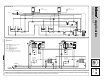
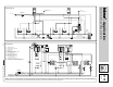
Domestic Hot Water (DHW) When the DHW tank requires heat, the DHW aquastat (A1) energizes relay R2. Relay R2 provides power
to the DHW pump (P2) and turns off the boiler pump (P1) in order to provide DHW priority. Once energized, relay R2 also enables the
boiler. The boiler is then allowed to operate up to the operating aquastat’s setting.
Boiler Demand When heat is required in the boiler zones, the zone valve end switches send a
Boiler Demand
to the 256 and energizes
relay R1. Provided the DHW aquastat (A1) is satisfied, relay R1 then turns on the boiler pump (P1). The boiler supply water temperature
is based on the
Characterized Heating Curve
settings. The boiler is fired to satisfy the required boiler supply water temperature. Whenever
the boiler is fired, the 256 aims to increase the boiler supply water temperature to at least the BOIL MIN setting.
Mixing Demand When heat is required in the mixed zones, the zone valve end switches send a
Mixing Demand
to the 356 and energizes
relay R3. Provided the DHW aquastat (A1) is satisfied, relay R3 then turns on the boiler pump (P1) and mixing system pump (P4). The
mixed supply water temperature is based on the
Characterized Heating Curve
settings. The variable speed injection pump (P3) is then
controlled to supply the required mixed supply water temperature. As the variable speed injection pump ramps up, the 356 uses its
Boiler
contact (terminals 5 and 6) to send a
Boiler Demand
to the 256. While the 356 is sending a
Boiler Demand
to the 256, the variable speed
injection pump (P3) is also modulated to protect the boilers from excessively low water temperatures.
All control functions and specifications are listed in the Product Catalog I 000 and Data Brochures D 356 and D 256.