
Application Brochure


1 of 12
- Application
Mixing Control 356
A 356-1
05/00
Copyright ©2000 A 356-1 -05/00
Note:
This is only a concept drawing. The designer must determine whether this application will work in his system and must ensure compliance with
code requirements. Necessary auxiliary equipment, isolation relays (for loads greater than the specified tekmar internal relay ratings), and other safety
and limit devices must be added.
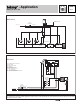
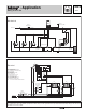
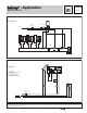
Mechanical
M
MM
see Essay E 021
Outdoor
Sensor (S2) 070
Class II
Transformer
120 V (ac)
24 V (ac)
P1
Mix
Sensor
(S1) 071
Boiler
Sensor
(S3) 071
P2
P3
R1
V1
T1T2T3
Z1Z2Z3
356
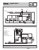
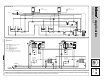
Electrical
P1 = Variable Speed Injection Pump
P2 = Boiler Pump
P3 = Mixing System Pump
R1 = Relay 003
S1 = Mix Supply Sensor 071
S2 = Outdoor Sensor 070
S3 = Boiler Supply Sensor 071
T1, ..., T3 = Thermostats
V1 = Balancing or Globe Valve
Z1, ..., Z3 = Zone Valve Motor End Switches
356
5
7
9
8
6
T
5A
Boiler
R+
C-
Power
Do not apply power
2
Out
3
Sup
Com
14
Boil
2.4A
S2
S3
S1
C
R
Boiler
P1
Zone Valve
Motor End
Switches
Z1
Z2
Z3
3
4
6
5
7
2
1
8
24 V (ac)
120 V (ac)
Class II
Transformer
N
L
R1
P2
P3