
Wiring Guide


7 of 12 © 2008 W 346 - 12/08
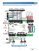
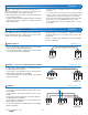
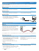
Connect Bus 3 tN4 terminal (13) to Bus 3 tN4 on the
Reset Module.
Connect Bus 3 C terminal (14) to Bus 3 C on the Reset
Module.
Connect Bus 3 tN4 (terminal 13) to the tN4 terminal on
the Mixing Expansion Module.
Connect Bus 3 C (terminal 14) to the C terminal on the
Mixing Expansion Module.
Connect R (terminal 15) to the R terminal on the Mixing
Expansion Module.
•
•
•
•
•
tN4 Bus 3 Terminals 13, 14, 15
tN4 C R
Mixing Expansion
Module
tN4 C R
3
13 14 15
Power
Manager 346
tN4 C
Reset
Module
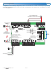
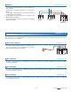
To create a demand on the boiler bus, a voltage between
24 V (ac) and 230 V (ac) must be applied across the Boil
Bus 0 Demand terminals (21 and 22).
•
Boiler Bus 0 Demand Terminals 21, 22
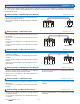
Wiring the Bus Demands Terminals 16 - 22
Each tN4 Bus has a corresponding Bus Demand input. When a Bus Demand is powered, the Power Manager sends a
message on the corresponding tN4 bus to activate the Reset Module. This allows non-communicating thermostats to be
able to call for heat on a tN4 bus.
To create a demand on bus 1, a voltage between 24 V (ac) and 230 V (ac) must be applied across the Bus 1 Demand
terminals (19 and 20).
•
Bus 1 Demand Terminals 19, 20
To create a demand on bus 2, a voltage between 24 V (ac) and 230 V (ac) must be applied across the Bus 2 Dem and
Com Dem terminals (18 and 17).
•
Bus 2 Demand Terminals 17, 18
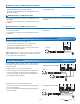
To create a demand on bus 3, a voltage between 24 V (ac) and 230 V (ac) must be applied across the Dem 3 and Com
Dem terminals (16 and 17).
•
Bus 3 Demand Terminals 16, 17
Boil 0
Demand
21 22
C R
14 15
Power Manager 346