
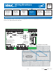
Wiring Guide


© 2008 W 346 - 12/08 4 of 12
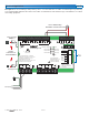
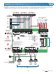
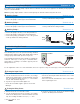
Electrical Application 346 E1
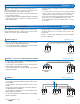
Description: The Power Manager 346 provides power to a reset module. An on-off Bus 1 Demand signal is provided by
non-communicating equipment. The 346 receives a Bus 1 Demand and sends a tN4 message on the tN4 Bus 1 to activate
the heating equipment.
115 V (ac)
L
G
N
Plug-in
Connections to
Left Side Module
Non-communicating
End-switch or thermostat call
115 V (ac) L & N
24 V (ac) R & C
tN4 Bus 1
See
D
346
tektra 1019-01
1
Power Manager 346
For product literature:
www.tekmarcontrols.com
Boiler Bus 0 Demand Power
Aux Pump 1
Aux Pump 2
Aux Pump 3
tN4
Bus 1 Demand
Bus 2 Demand
Bus 3 Demand
Meets Class B: Canadian
ICES & FCC Part 15
Caution! Disconnect All
Power before Opening
24 V (ac) Fuse: T2.5 A 250 V
H7011A
Relay Power
27 28
NL
Aux Pump 2
29 30
NPmp
Aux Pump 3
31 32
NPmp
For product instructions, see brochure
Input Power: 115 V (ac) ±10% 60 Hz, 12 A
All Loads Using Input Power: 11.5 A
Relay Ratings: 115 V (ac) 5 A
Relay Power: 115 V (ac) ±10% 60 Hz, 10 A
Demands: 20 to 260 V (ac) 2 VA
Supply wires 90°C/105°C
See manual
Boil Bus
0
16 17
Demand
Bus
3 Bus
2
18
Dem DemDem
19
Bus 1
20 21
Demand
227
tN4
56
t
N
4C C
12
Boil 0
11
tN4
910
2
CC
15
tN4
13 14
3
ComAux
Pmp1
4
R
R R R
3
Aux
Pmp2
8
Aux
Pmp3
12
Limited power available, see wiring brochure
Room Occ
Room UnOcc
0Boil
1
2
3
1
3
11
9
7
5
12
10
8
6
4
2
Schedule
Member
Input Power
23 24
NL
Aux Pump 1
25 26
NPmp