
Wiring Guide


3 of 12 © 2008 W 346 - 12/08
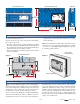
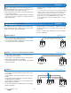
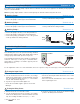
Mounting the Enclosure
Figure 2
Custom Panel
or Electrical Box
Wall or Panel Door
To mount the wiring enclosure:
Remove the front cover of the enclosure by removing the
two screws in the cover.
Place the enclosure in the location decided upon during
the rough-in wiring stage. Wiring will enter through either
the top and bottom knockouts or through the back upper
and lower knockouts. See figures 1 and 2.
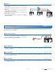
There are twelve holes in the back of the enclosure that
allow for mounting.
•
•
Using screws, ensure that the enclosure is securely
fastened in place.
Note: The nonmetallic conduit entries in the back of the
enclosure do not provide grounding between conduit
connections. Use bonding bushings and jumpers to provide
a continuous path to ground.
•
Figure 1
7
1
/8
”
(18
1 mm)
Ground
Screws
10
3
/16
”
(259 mm)
Screw hole
Dimensions
4
1
/4
”
(108 mm)
(108 mm)
4
1
/4
”
(108 mm)
2
3
/4
”
”
(70 mm)
(70 mm)
3
7
/8
”
(99 mm)
2
15
/16
”
(74 mm)
Side View
tektra 1019-01
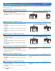
Power Manager 346
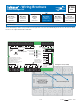
For product literature:
www.tekmarcontrols.com
Boiler Bus 0 Demand Power
Aux Pump 1
Aux Pump 2
Aux Pump 3
tN4
Bus 1 Demand
Bus 2 Demand
Bus 3 Demand
Caution! Disconnect All
Power before Opening
For product instructions, see brochure
Input Power: 115 V (ac) ±10% 60 Hz, 12 A
All Loads Using Input Power: 11.5 A
Relay Ratings: 115 V (ac) 5 A
Relay Power: 115 V (ac) ±10% 60 Hz, 10 A
Demands: 20 to 260 V (ac) 2 VA
11
1
/8
”
(282 mm)
8
1
/16
”
(204 mm)
1
5
/16
”
(33 mm)
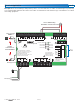
Front View without Cover
tektra 1019-01
1
Power Manager 346
For product literature:
www.tekmarcontrols.com
Boiler Bus 0 Demand Power
Aux Pump 1
Aux Pump 2
Aux Pump 3
tN4
Bus 1 Demand
Bus 2 Demand
Bus 3 Demand
Meets Class B: Canadian
ICES & FCC Part 15
Caution! Disconnect All
Power before Opening
24 V (ac) Fuse: T2.5 A 250 V
H7011A
Relay Power
27 28
N
L
Aux Pump 2
29 30
N
Pmp
Aux Pump 3
31 32
N
Pmp
For product instructions, see brochure
Input Power: 115 V (ac) ±10% 60 Hz, 12 A
All Loads Using Input Power: 11.5 A
Relay Ratings: 115 V (ac) 5 A
Relay Power: 115 V (ac) ±10% 60 Hz, 10 A
Demands: 20 to 260 V (ac) 2 VA
Supply wires 90°C/105°C
See manual
Boil Bus
0
16 17
Demand
Bus
3Bus
2
18
Dem DemDem
19
Bus 1
20 21
Demand
227
tN4
56
t
N
4C C
12
Boil 0
11
tN4
910
2
CC
15
tN4
13 14
3
ComAux
Pmp1
4
R
R R R
3
Aux
Pmp2
8
Aux
Pmp3
12
Limited power available, see wiring brochure
Room Occ
Room UnOcc
0Boil
1
2
3
1
3
11
9
7
5
12
10
8
6
4
2
Schedule
Member
Input Power
23 24
N
L
Aux Pump 1
25 26
N
Pmp
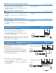
Front View with Cover
Screw Hole Dimensions
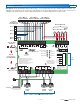
Electrical Drawings
The electrical drawing examples on the following pages
show the 346 in common applications. These drawings
have a brief explanation of what is being operated in each
system. Choose the components in your system and use
the drawings as a guide to aid in wiring your system.
These are only concept drawings, not engineered drawings.
They are not intended to describe a complete system nor
any particular system. It is up to the system designer to
determine the necessary components for and configura-
tion of the particular system being designed including
additional equipment isolation relays (for loads greater
than the controls specified output ratings) and any safety
devices which in the judgement of the designer are ap-
propriate in order to properly size, configure and design
that system and to ensure compliance with building and
safety code requirements.