
Wiring Guide


© 2008 W 346 - 12/08 10 of 12
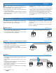
Connect the pump’s line in (L) to the Pmp terminal 25.
Connect the pump’s neutral (N) to the N terminal 26.
•
•
Connect the pump ground wire to one of the ground
screws provided in the wiring chamber.
•
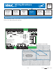
Auxiliary Pump 1 Terminals 25, 26
Wiring the Auxiliary Pump Outputs Terminals 25 - 32
The 346 has three Auxiliary Pump outputs that are activated once 24 V (ac) is applied to the Auxiliary Pump input from
any one of the R terminals.
Note: For pumps larger than the control’s rated capacity, an external isolation relay must be used.
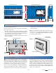
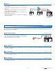
Connect the pump’s line in (L) to the Pmp terminal 29.
Connect the pump’s neutral (N) to the N terminal 30.
•
•
Connect the pump ground wire to one of the ground
screws provided in the wiring chamber.
•
Auxiliary Pump 2 Terminals 29, 30
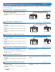
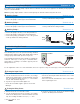
Connect the pump’s line in (L) to the Pmp terminal 31.
Connect the pump’s neutral (N) to the N terminal 32.
Connect the pump ground wire to one of the ground
screws provided in the wiring chamber.
•
•
•
Auxiliary Pump 3 Terminals 31, 32
General
The following tests are to be performed using standard
testing practices and procedures and should only be carried
out by properly trained and experienced persons.
A good quality electrical test meter, capable of reading from
at least 0 - 300 V (ac), 0 - 30 V (dc), 0 - 2,000,000 Ohms,
and testing for continuity is essential to properly test the
wiring and sensors.
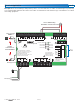
Troubleshooting the Control
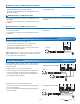
Testing the Input Power Terminals 23, 24
Testing the Relay Power Terminal 27, 28
1. Remove the front cover from the control.
2. Use an electrical test meter to measure (ac) voltage
between the Relay Power L and N terminals (27 and
28). The reading should be 115 V (ac) + / – 10%.
3. If power is not present, check the circuits that supply
power to the Relay Power terminals.
Test Meter
###
Control Terminals
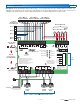
1. Remove the front cover from the control.
2. Use an electrical test meter to measure (ac) voltage
between the Input Power L and N terminals (23 and
24). The reading should be 115 V (ac) + / – 10% and the
“Power” LED should be lit green.
3. If power is not present and the light is off:
Check the circuit that supplies power to the Power
Manager.
•
4. If power is present but the ‘Power’ LED is lit amber:
Check the field replaceable transformer fuse on the
Power Manager.
If the fuse is blown, determine the cause of the failure
before replacing the fuse.
•
•
For an explanation on the use of the Test Button, the ‘Test’ sequence or any error messages, refer to the Data Brochure.
Pump
Pump
L & N
31 32
Aux Pump 3
Pmp N