
Submittal Sheet
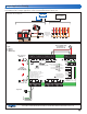

Below is a sample application drawing for this product. This application may include other tekmar products that are required
for installation. More sample applications can be found at www.tekmarcontrols.com.
Sample Electrical diagram
Sample Mechanical diagram
Product design, software and literature are Copyright © 20 by:
tekmar Control Systems Ltd. and tekmar Control Systems, Inc.
2 of 2
All specifications are subject to change without notice.
Printed in Canada. C 346 - 0/.
tekmar Control Systems Ltd., Canada, tekmar Control Systems, Inc., U.S.A.
tektra 1019-01
1
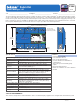
Power Manager 346
For product literature:
www.tekmarcontrols.com
Boiler Bus 0 Demand Power
Aux Pump 1
Aux Pump 2
Aux Pump 3
tN4
Bus 1 Demand
Bus 2 Demand
Bus 3 Demand
Meets Class B: Canadian
ICES & FCC Part 15
Caution! Disconnect All
Power before Opening
24 V (ac) Fuse: T2.5 A 250 V
H7011A
Relay Power
27 28
NL
Aux Pump 2
29 30
NPmp
Aux Pump 3
31 32
NPmp
For product instructions, see brochure
Input Power: 115 V (ac) ±10% 60 Hz, 12 A
All Loads Using Input Power: 11.5 A
Relay Ratings: 115 V (ac) 5 A
Relay Power: 115 V (ac) ±10% 60 Hz, 10 A
Demands: 20 to 260 V (ac) 2 VA
Supply wires 90°C/105°C
See manual
Boil Bus
0
16 17
Demand
Bus
3 Bus
2
18
Dem DemDem
19
Bus 1
20 21
Demand
227
tN4
5 6
t
N
4 C C
1 2
Boil 0
11
tN4
9 10
2
C C
15
tN4
13 14
3
ComAux
Pmp1
4
RR R R
3
Aux
Pmp2
8
Aux
Pmp3
12
Limited power available, see wiring brochure
Room Occ
Room UnOcc
0Boil
1
2
3
1
3
11
9
7
5
12
10
8
6
4
2
Schedule
Member
Input Power
23 24
NL
Aux Pump 1
25 26
NPmp
070
423 346
Heat Demand
created by 346.
Heating System
by 423