
Install Instructions


5 of 8 © 2008 D 346 - 04/08
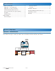
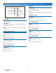
Switch Settings
Room Occupied
The Room Occupied can be set to one of four temperatures
using the following switch setting pair combinations:
Temperature
75°F
(24.0°C)
72°F
(22.0°C)
68°F
(20.0°C)
65°F
(18.5°C)
Room
Occupied
12
12
11
11
12
12
11
11
12
12
11
11
12
12
11
11
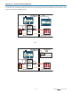
Room Unoccupied
The Room Unoccupied can be set to one of four temperatures
using the following combinations:
Temperature
50°F
(10.0°C)
55°F
(13.0°C)
60°F
(15.5°C)
65°F
(18.5°C)
Room
Unoccupied
10
10
9
9
10
10
9
9
10
10
9
9
10
10
9
9
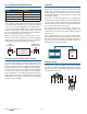
Schedules
For each tN4 bus, there are a pair of switches that determine
which schedule master to follow as a schedule member.
Member of Schedule
Bus Off 123
tN4
Boiler
Bus 0
8
7
8
7
8
7
8
7
tN4
Bus 1
6
5
5
6
5
5
6
5
5
6
5
tN4
Bus 2
4
3
4
3
4
3
4
3
tN4
Bus 3
2
1
1
2
1
1
2
1
1
2
1
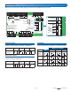
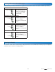
With the cover removed, the switch settings are located on the right hand side of the 346.
tektra 1019-01
1
Power Manager 346
For product literature:
www.tekmarcontrols.com
Boiler Bus 0 Demand Power
Aux Pump 1
Aux Pump 2
Aux Pump 3
tN4
Bus 1 Demand
Bus 2 Demand
Bus 3 Demand
Meets Class B: Canadian
ICES & FCC Part 15
Caution! Disconnect All
Power before Opening
24 V (ac) Fuse: T2.5 A 250 V
H7011A
Relay Power
27 28
N
L
Aux Pump 2
29 30
N
Pmp
Aux Pump 3
31 32
N
Pmp
For product instructions, see brochure
Input Power: 115 V (ac) ±10% 60 Hz, 12 A
All Loads Using Input Power: 11.5 A
Relay Ratings: 115 V (ac) 5 A
Relay Power: 115 V (ac) ±10% 60 Hz, 10 A
Demands: 20 to 260 V (ac) 2 VA
Supply wires 90°C/105°C
See manual
Boil Bus
0
16 17
Demand
Bus
3 Bus
2
18
Dem DemDem
19
Bus 1
20 21
Demand
227
tN4
56
t
N
4C C
12
Boil 0
11
tN4
910
2
CC
15
tN4
13 14
3
Com
Aux
Pmp1
4
R
R R R
3
Aux
Pmp2
8
Aux
Pmp3
12
Limited power available, see wiring brochure
Room Occ
Room UnOcc
0Boil
1
2
3
1
3
11
9
7
5
12
10
8
6
4
2
Schedule
Member
Input Power
23 24
N
L
Aux Pump 1
25 26
N
Pmp
Room Occ
Room UnOcc
0Boil
1
2
3
1
3
11
9
7
5
12
10
8
6
4
2
Schedule
Member