
Job Record

1 of 2 © 2009 J 336 - 08/09
J 336
08/09
- Job Record
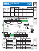
Zone Manager 336
Zone Manager 336
Meets Class B: Canadian
ICES & FCC Part 15
Made in Canada
Supply
/signal wires 90°C min.
Zone A1
Zone A2
Power
Zone Group Pump A
Zone A3
Zone A4
tN4
tektra 997-01
Input Power: 115 V (ac) ±10% 60 Hz, 12 A
Relay Rating: 115 V (ac) 5 A
All Loads Using Input Power: 11.7 A
Zone Power: 115 V (ac) ±10% 60 Hz, 12 A
For product instructions, see brochure
Caution! Disconnect All
Power before Opening
Limited power available, see wiring brochure
For product literature:
www.tekmarcontrols.com
1
23456789101112 13 14 15 16 17 18 19
24 V (ac) Fuse: T1.25 A 250 V
On/Off
tN4 C C CWWRRPmp tN4 tN4 C WRtN4 C WRtN4
Zn Grp A A tNt Zone A1 tNt Zone A2 tNt Zone A3 tNt Zone A4
20 21 22
23
Input Power Zone Group
N
L
N
Pmp A
30 31 32
33
Zone A3 Zone A4
N
Pump
N
Pump
26 27 28
29
Zone A1 Zone A2
N
Pump
N
Pump
24
25
Zone Power
N
L
Zone Group
Pump A
A1
A2
A3
A4
H7004B
Zone A1 A2 A3 A4
Label
Thermostat
Model
Schedule
Heat / Cool
Cool Group
Address
VA
+ + +
Zone
Group A
External
tN4
Input /
Output
Zone
Group
Pump A
Input
Control
Label
Model
Location
Bus #
VA from left side module
Zone Group
Pump
A
Label
Make
Model
Amps
Design
Flow
Design
Head
Zone Pump
A1 A2 A3 A4
Label
Make
Model
Amps
+ + +
Design
Flow
Notes
Total
Zone
Pump
Amps
115 V (ac)
Combined
Total
Amps
Max. 11.7 A
Control Name / Location Connected to Module
(Max. 5 A)
Line
Voltage
Input
115 V (ac)
A1
On Off
A2
On Off
A3
On Off
A4
On Off
Dip Switch
Settings
(circle / fi ll-in the
correct setting)
Zone Group
Pump A
If using same
power as
terminals 20-21
then add to
the left
Line
Voltage
Input
115 V (ac)
use separate
breaker if
required
If using
separate
power then
add to
the right
(Max. 5 A) (Max. 5 A) (Max. 5 A) (Max. 5 A)
Max.
12 Amps
on separate
breaker
+
Total
Tstat +
Left Side
Module
VA
Max.
24 VA
24 V (ac)
See
W 336 to
add extra
VA