
Wiring Guide


© 2008 W 335 - 12/08 8 of 12
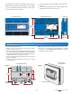
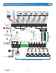
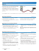
Provide a 15 Amp circuit for the power input.
Wire 115 V (ac) power to terminals 28 and 29.
•
• Connect 115 V hot (L) to terminal 28.
•
• Connect 115 V neutral (N) to terminal 29.
•
• Connect the ground wire to one of the ground screws
provided in the wiring chamber.
Wiring the Input Power Terminals 28-29
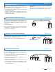
The 335 operates one Zone Group Pump.
•
• If a Zone Group Pump A is used, the pump is wired
directly to terminals 30 and 31.
•
• The pumps’ ground wires are connected to the ground
screw provided in the wiring chamber.
Note: For pumps larger than the control’s rated capacity,
an external isolation relay must be used.
Wiring the Zone Group Pump Terminals 30-31
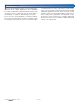
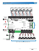
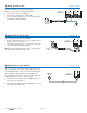
Up to six 24 V (ac) zone valves may be wired to the 335.
The maximum load for each zone valve is determined by
the relay rating of the thermostat operating that zone.
Two terminals are provided for each zone valve. These two
terminals provide 24 V (ac) to the zone valve.
•
• Connect the C terminal on the Zone Manager to one
wire of the zone valve motor.
•
• Connect the Vlv terminal on the Zone Manager to second
wire on the zone valve motor.
Wiring the Zone Valve Outputs Terminals 32-43
32 33
Zone A1
C
Vlv
Zone Valve
Motor
Zone
Manager 335
N
G
L
115 V (ac)
28 29 30 31
Input Power Zone Group
L N Pmp A N
Zone
Manager 335
Ground
Zone
Manager 335
Pump
Pump
L & N
30 31
Zone Group
Pmp A N
Ground