
Wiring Guide


3 of 12 © 2008 W 335 - 12/08
The wiring enclosure allows for easy wiring of devices as the
upper and lower chambers provide ample room for wiring.
•
• Use the conduit knockouts provided on the upper, lower,
back and sides of the enclosure.
•
• Thermostat wiring enters through the upper half of the
enclosure.
•
• Power, zone group pump, and zone valve wiring enters
through the lower half of the enclosure.
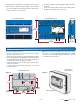
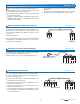
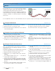
Mounting the Enclosure
Figure 2
Custom Panel
or Electrical Box
Wall or Panel Door
To mount the wiring enclosure;
•
• Remove the front cover of the enclosure by removing
the two screws in the cover.
•
• Place the enclosure in the location decided upon during
the rough-in wiring stage. Wiring will enter through either
the top and bottom knockouts or through the back upper
and lower knockouts. See figures 1 and 2.
•
• There are twelve holes in the back of the enclosure that
allow for mounting.
•
• Using screws, ensure that the enclosure is securely
fastened in place.
Note: The nonmetallic conduit entries in the back of the
enclosure do not provide grounding between conduit
connections. Use bonding bushings and jumpers to provide
a continuous path to ground.
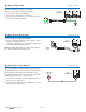
Figure 1
7
1
/8
”
(181 mm)
Ground
Screws
10
3
/16
”
(259 mm)
Screw hole
Dimensions
4
1
/4
”
(108 mm)
(108 mm)
4
1
/4
”
(108 mm)
2
3
/4
”
”
(70 mm)
(70 mm)
3
7
/8
”
(99 mm)
2
15
/16
”
(74 mm)
Side View
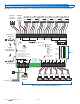
Zone Manager 335
Zone A1
Zone A2
Power
Zone Group Pump A
Zone A3
Zone A4
Zone A5
Zone A6
tN4
tektra 996-01
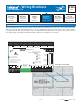
For product instructions, see brochure
Input Power: 115 V (ac) ±10% 60 Hz 12 A
Relay Rating: 115 V (ac) 5 A
All Loads Using Input Power: 11.5 A
Caution! Disconnect All
Power before Opening
For product literature:
www.tekmarcontrols.com
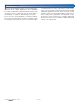
11
1
/8
”
(282 mm)
8
1
/16
”
(204 mm)
1
5
/16
”
(33 mm)
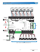
Front View without Cover
Zone Manager 335
Meets Class B:
Canadian ICES &
FCC Part 15
Made in Canada
Zone A1
Zone A2
Power
Zone Group Pump A
Zone A3
Zone A4
Zone A5
Zone A6
tN4
tektra 996-01
For product instructions, see brochure
Input Power: 115 V (ac) ±10% 60 Hz 12 A
Relay Rating: 115 V (ac) 5 A
All Loads Using Input Power: 11.5 A
Caution! Disconnect All
Power before Opening
Limited power available, see wiring brochure
For product literature:
www.tekmarcontrols.com
1
23456789101112 13 14 15 16 20
H7003B
32 33 34 35 36 37 38 39 40 41 42 43
17 18 19
21 22 23 24
25
26 27
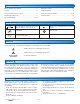
24 V (ac) Fuse: T2.5 A 250 V
28 29 30
31
On/Off
Zone Group
Pump A Delay
Zone Group
Pump A
A1
A2
A3
A4
A5
A6
A1
A2
A3
A4
A5
A6
tN4 C C CWWRRPmp tN4 tN4 C WRtN4 C WRRtN4 C WtN4 RCWtN4
Input Power Zone Group Zone A1 Zone A2 Zone A3 Zone A4 Zone A5 Zone A6
Zn Grp A A tNt Zone A1 tNt Zone A2 tNt Zone A3 tNt Zone A4 tNt Zone A5 tNt Zone A6
N
L
N
Pmp A
C
Vlv
C
Vlv
C
Vlv
C
Vlv
C
Vlv
C
Vlv
Supply
/signal wires 90°C min.
Front View with Cover
Scre
w Hole Dimensions