
Wiring Guide


tekmar Control Systems Ltd., Canada
tekmar Control Systems, Inc., U.S.A.
Head Office: 5100 Silver Star Road
Vernon, B.C. Canada V1B 3K4
(250) 545-7749 Fax. (250) 545-0650
Web Site: www.tekmarcontrols.com
Product design, software and literature are Copyright © 2008 by:
tekmar Control Systems Ltd. and tekmar Control Systems, Inc.
8 of 8
All specifications are subject to change without notice.
Printed in Canada. W 326 - 12/08.
The installer must ensure that this control and its wiring are isolated and/or shielded from strong sources of electromagnetic
noise. Conversely, this Class B digital apparatus complies with Part 15 of the FCC Rules and meets all requirements of the
Canadian Interference-Causing Equipment Regulations. However, if this control does cause harmful interference to radio
or television reception, which is determined by turning the control off and on, the user is encouraged to try to correct the
interference by re-orientating or relocating the receiving antenna, relocating the receiver with respect to this control, and/or
connecting the control to a different circuit from that to which the receiver is connected.
Cet appareil numérique de la classe B respecte toutes les exigences du Règlement sur le matériel brouilleur du Canada.
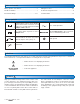
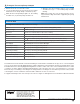
Zone Expansion Module 326; Three Zone Pumps
Control Microprocessor PID control; This is not a safety (limit) control
Packaged weight 2.98 lb. (1350 g)
Dimensions 3-5/8” H x 5-3/8” W x 9/16” D (92 x 137 x 14 mm)
Approvals CSA C US, CSA/UL 61010-1, meets Class B: ICES and FCC Part 15
Ambient conditions Indoor use only, 32 to 122°F (0 to 50°C)
RH 80% to 88°F (31°C), down to 50% from 104 to 122°F (40 to 50°C)
Altitude <6560 feet (2000 m), Installation Category II, Pollution Degree 2
Power Supply Provided by interconnected Zone Manager
Zone Pump C1 Relay 115 V (ac) 5 A 1/4 hp, pilot duty 240 VA
Zone Pump C2 Relay 115 V (ac) 5 A 1/4 hp, pilot duty 240 VA
Zone Pump C3 Relay 115 V (ac) 5 A 1/4 hp, pilot duty 240 VA
Zone Group Pump C Relay 115 V (ac) 5 A 1/4 hp, pilot duty 240 VA
Combined Relay Load 10 A Maximum
Combined Load on Input Power 10 Amp Maximum
Technical Data
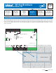
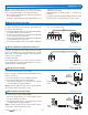
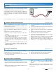
Testing the Zone Group Pump C Output Terminals 71, 72
1. Remove the front cover from the control.
2. Use an electrical test meter to measure the (ac) voltage
between the Zone Group Pump C terminals (71-72).
•
• When the Zone Group Pump C light is off, the reading
should be 0 V (ac) and the pump should be off.
•
• When the Zone Group Pump C light is on, the reading
should be 115 V (ac) + / – 10% and the pump should be
running.
Note: If the pump does not operate properly, refer to
any troubleshooting information supplied by the pump
manufacturer.