
Wiring Guide


© 2008 W 326 - 12/08 6 of 8
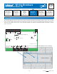
This section explains how to wire individual devices to
the Zone Expansion Module 326. For step by step wiring
refer to the terminal number on the right of the page.
•
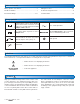
• Before wiring ensure all power is turned off and take all
necessary precautions.
•
• Install the supplied wiring compartment barriers by
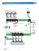
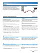
Terminals 63 and 64 provide a tN4 connection for tN4
devices on the tN4 bus. Connect terminals 63 (C) and 64
(tN4) to the corresponding terminals on the tN4 devices
that are to be connected.
Polarity is important.
Ensure that terminal 63 (C) is connected to the C terminal
on the tN4 device and that terminal 64 (tN4) is connect to
the tN4 terminal on the tN4 device.
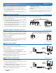
Wiring tekmarNet
®
4 (tN4) between Devices Terminals 63, 64
Up to three tekmarNet
®
4 (tN4) thermostats may be wired to
the 326. Four terminals are provided for each thermostat.
For each of the thermostats,
•
• Connect the tN4 terminal on the Zone Expansion Module
to the tN4 terminal on the thermostat.
•
• Connect the C terminal on the Zone Expansion Module
to the C terminal on the thermostat.
•
• Connect the R terminal on the Zone Expansion Module
to the R terminal on the thermostat.
•
• Connect the W terminal on the Zone Expansion Module
Wiring the Thermostats (tN4) Terminals 51-62
Wiring the Control Terminals 51-72
sliding them into the grooves provided to isolate the low
and high voltage wiring.
•
• Strip all wiring to a length of 3/8 in. or 10 mm for all
terminals.
•
• Refer to the current and voltage ratings at the back of this
brochure before connecting devices to this control.
tN4 C R W
tNt Zone A1
51 52 53 54
tN4 C R Rh1 W1
Zone Expansion
Module 326
(internal jumper)
Thermostat
C tN4
C tN4
Zn Grp C
63 64
other tN4
control
Zone Expansion
Module 326
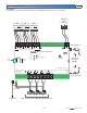
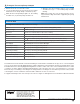
The 326 operates one Zone Group Pump.
•
• If the Zone Group Pump C is used, the pump is wired
directly to terminals 71 and 72.
•
• The pump ground wires is connected to the ground
screw provided in the wiring chamber.
Note: For pumps larger than the control’s rated capacity,
an external isolation relay must be used.
Wiring the Zone Group Pump Terminals 71-72
Zone
Expansion
Module 326
Pump
Pump
L & N
The 326 operates up to three Zone Pumps.
Each zone pump is wired to a Pump and N terminal on the
326. For each zone,
•
• Connect the pump’s (L) to the (Pump) terminal.
•
• Connect the pump’s (N) to the (N) terminal.
•
• The pump ground wires are connected to the ground
screw provided in the wiring chamber.
Note: For pumps larger than the control’s rated capacity,
an external isolation relay must be used.
Wiring the Zone Pumps Terminals 65-70
Zone
Expansion
Module 326
Pump
Pump
L & N
65 66
Zone C1
Pump N
71 72
Zone Group
Pmp C N
to the W or W1 terminal on the thermostat (or W2 in the
case of second stage heat).