
Install Instructions

3 of 4 © 2005 D 326 - 06/05
DIP Switches
DIP Switch Settings
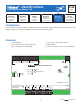
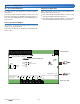
The DIP switches are found on the left hand side of the 326.
NN
Zone C1 Zone C2
65 66 67 68
Pump Pump
tN4
Meets Class B: Canadian
ICES & FCC Part 15
Made in Canada
10 A (max)
Zone Expansion Module 326
tektra 999-01
Relay Rating: 115 V (ac) 5 A
N
Zone C3
69 70
Pump N
Zone Group
71 72
Pmp C
Power
Zone Group Pump C
Zone C1
Zone C2
Zone C3
51 52 53 54 55 56 57 58 59 60 61 62
CCWWRRtN4 tN4 C WRtN4
tNt Zone C1 tNt Zone C2 tNt Zone C3
63
64
C tN4
Zn Grp C
C1
C2
On/Off
Zone Group
Pump C
C3
Limited power available, see wiring brochure
H7002B
C1
C2
On/Off
Zone Group
Pump C
C3
Zone Group Pump
Each zone has a corresponding Zone Group Pump DIP
switch.
Zone Group Pump DIP switch set to On:
•
• The Zone Group Pump turns on when the zone calls for
heat.
Zone Group Pump DIP switch set to Off:
•
• The Zone Group Pump does not turn on when the zone
calls for heat.
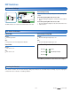
LED Status Indicators
Zone Expansion Module 326
Power
Zone Group Pump C
Zone C1
Zone C1
Zone C1
Power LED
Green:
•
• Normal operation.
Off:
•
• No power to the Zone Expansion Module.
Zone LEDs
Green:
•
• The zone is on.
Off:
•
• The zone is off.
Zone Group Pump LED
Green:
•
• The Zone Group Pump relay is on.
Off:
•
• The Zone Group Pump relay is off.
Five LEDs to provide the status of the 326’s outputs.
Cleaning the Control
The control’s exterior can be cleaned using a damp cloth. Moisten the cloth with water and wring out prior to wiping the
control. Do not use solvents or cleaning solutions.