
Wiring Guide

Q316
04/09
1 of 2 © 2009 Q 316 - 04/09
tN4 Wiring Center 316
Quick Setup Guide
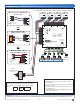
Wire the Thermostats
•
• Connect tN4, C, R and W conductors to the corresponding
terminals on the 316, paying special attention to ensure that
the tN4 and C wires are not reversed. See the labelling shown
in Figure 3.
Control Location
•
• The Wiring Center must be mounted directly to a 4”x4” electrical
box to allow for pump wiring connections.
•
• All 115 V (ac) pump wiring will enter into the electrical box.
•
• Thermostat and low-voltage wires will enter through either side
knockouts or between the base of the enclosure and the cover
on the sides and top. See Figure 3.
Note: The nonmetallic enclosure does not provide grounding
between conduit connections. Conduit connections must be
grounded by other means.
Power
Zone 1
Zone 2
Zone 3
Zone 4
End Sw
i
tch
C
Zone 2
WtN
4
R
C
Zone 3
WtN
4
R
C
Zone 4
WtN4
R
tN4 W
iring Center 316
Four Zone P
um
ps
WtN4CtN4C
Zone 1
Expansion
End Switch
C
Input Power
R
R
H80
02A
X
X
In
put Power:
24 V (ac) ±10%
60 Hz
11
V
A Cla
ss 2
End Swi
tc
h
:
24
V (ac) 2 A
Pump Relays: 115 V (ac) 5 A
Zone P
ow
er: 1
1
5 V (ac) 12 A
M
ade
in Ca
n
ada
tektra 1
031-01
Use at
least 167°F (75°C) conduc
tor
s
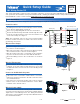
Wire the Zone Pumps
•
• Wire line voltage to the red zone power lead (L) at the back of
the control as shown in Figure 1.
•
• Wire each zone pump’s 115V connection to the black zone pump
wires at the back of the control as shown in Figure 1.
•
• Wire the neutral connection of each pump to the neutral line
(N) of the electrical circuit. Do the same with Ground wires.
•
• Mount the Wiring Center to the electrical box as shown in
Figure 2.
115 V (ac)
LNG
Zone 1
Zone 2
Zone 3
Zone 4
Zone Power L
Zone 1
Zone 2
Zone 3
Zone 4
Pump
Pump
Pump
Pump
to pump grounds
N
L
Back of Wiring Center
Basic Installation
This Quick Setup Guide contains the basic information required to get your new tekmar tN4 Wiring Center 316 installed
and operational. An Installation and Operation Manual D316 containing all available features and operational details is
included with this control or can be found at www.tekmarcontrols.com/literature.html
The tN4 Wiring Center 316 is designed to operate 4 zone pumps in a hydronic heating system.
Connect to the Mechanical System
•
• If the 316 is to be connected to a tN4 network, connect the
tN4 and C expansion terminals to the tN4 connection on the
associated tN4 device.
•
• If the 316 is to be connected to another control, such as a tekmar
Boiler Control, use the end switch terminals to create a ‘Boiler
Demand’ on the external control.
Wire the Power Supply
Once the transformer has been correctly sized, connect the 24 V
(ac) leads from the transformer to the R and C terminals marked
“Input Power” on the Wiring Center. See “Sizing the External
Transformer” in the Installation and Operation Manual D316 for
more detailed information.
Figure 1
Figure 3
tN4 C R W
OUTDOOR
F
HEAT
FLOOR
F
Figure 2