
Wiring Guide

Q315
04/09
tN4 Wiring Center 315
1 of 2 © 2009 Q 315 - 04/09
- Quick Setup Guide
Control Location
•
• The Wiring Center can be mounted either directly to the wall,
or to a 4”x4” electrical box.
•
• Mount the enclosure to a solid backing.
•
• Wiring will enter through either side knockouts or between the
base of the enclosure and the cover on the sides and top. See
Figure 1 and Figure 2.
Note: The nonmetallic enclosure does not provide grounding
between conduit connections. Conduit connections must be
grounded by other means.
Use at least 16
7°F
(75°
C) conductor
s
Input Power:
24 V (ac) ±10% 60 Hz
2 V
A (98 VA max)
Clas
s 2
End Switch: 24 V (a
c) 2
A
Zone Output: 2 A
pe
r z
one
4 A (max) total
Power
Zone 1
Zone 2
Zone 3
Zone 4
Zone 5
Zone 6
End Switch
C
Zone 2
WtN4
R
C
Zone 3
WtN4
R
C
Zone 4
WtN4
R
tN4 Wiring Center 315
Six Zone Valves
W tN4CtN4CX
Zone 1 Expansion
Vlv
C
Zone 1
Vlv
C
Zone 2
Vlv
C
Zone 3
Vlv
C
Zone 4
Vlv
C
Zone 5
VlvC
Zone 6
XC
Input Power
R
R
W
tN4
C
Zone 5
RW
tN4
C
Zone 6
R
H8001
A
E
nd Switch
Made in Canada
tek
tra 1032-01
Basic Installation
Valve Valve Valve Valve Valve Valve
C Vlv C Vlv C Vlv C Vlv C Vlv C Vlv
tN4 C R W
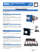
This Quick Setup Guide contains the basic information required to get your new tekmar tN4 Wiring Center 315 installed
and operational. An Installation and Operation Manual D 315 containing all available features and operational details is
included with this control or can be found at www.tekmarcontrols.com/literature.html
The tN4 Wiring Center 315 is designed to be mounted near a zone manifold and will operate up to 6 zone valves in a
hydronic heating system.
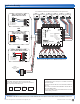
Wire the Thermostats
tN4 Thermostats:
•
• Connect tN4, C, R and W conductors to the corresponding
terminals on the 315, paying special attention to ensure that the
tN4 and C wires are not reversed. See the terminal labelling in
Figure 2.
Wire the Zone Valves
•
• Wire the zone valves to the Vlv and C terminals on the 315,
as shown in Figure 3.
•
• End switches on zone valves are not required when using
the 315.
Connect to the Mechanical System
•
• If the 315 is to be connected to a tN4 network, connect the
tN4 and C expansion terminals to the tN4 connection on the
associated tN4 device.
•
• If the 315 is to be connected to another control, such as a
tekmar Boiler Control, use the end switch terminals to create
a ‘Boiler Demand’ on this external control. See application on
next page.
Figure 1
Wire the Power Supply
Once the transformer has been correctly sized, connect the 24 V
(ac) leads from the transformer to the R and C terminals marked
“Input Power” on the Wiring Center. See “Sizing the External
Transformer” in the Installation and Operation Manual D 315 for
more detailed information.
Figure 2
Figure 3
OUTDOOR
F
HEAT
FLOOR
F