
Submittal

Below is a sample application drawing for this product. This application may include other tekmar products that are required
for installation. More sample applications can be found at www.tekmarcontrols.com.
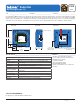
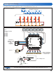
Sample Application Drawing
Sample Electrical diagram
Sample Mechanical diagram
Product design, software and literature are Copyright © 2011 by:
tekmar Control Systems Ltd. and tekmar Control Systems, Inc.
2 of 2
All specifications are subject to change without notice.
Printed in Canada. C 315 - 04/11.
tekmar Control Systems Ltd., Canada, tekmar Control Systems, Inc., U.S.A.
Head Offi ce: 5100 Silver Star Road,
Vernon, B.C. Canada V1B 3K4, 250-545-7749, Fax. 250-545-0650 Web Site: www.tekmarcontrols.com
R
C
L
N
115 V (ac)
L
N
G
to pump grounds
N
L
(red)
(black)
315
Power L
Zone Group Pump
Power
Zone 1
Zone 2
Zone 3
Zone 4
Zone 5
Zone 6
End Switch/ Zone Group Pump
C
Zone 2
WtN4 R
C
Zone 3
WtN4 R C
Zone 4
WtN4 R
tN4 Wiring Center 315
Six Zone Valves
W tN4C tN4CX
Zone 1 Expansion
VlvC
Zone 1
VlvC
Zone 2
VlvC
Zone 3
VlvC
Zone 4
VlvC
Zone 5
VlvC
Zone 6
XC
Input Power
RR
W tN4C
Zone 5
RW tN4C
Zone 6
R
H8001B
End Switch
Use at least 167°F
(75°C) conductors
Expansion
tN4
CtN4
Boiler
TT
315
Z1 Z2 Z3 Z4 Z5 Z6
tekmarNet
®
4 Thermostats
Legend
P1 = Zone Group Pump
Z1 = Zone 1
Z2 = Zone 2
Z3 = Zone 3
Z4 = Zone 4
Z5 = Zone 5
Z6 = Zone 6
Z1 Z2 Z3 Z4 Z5 Z6
tekmarNet
®
4 Thermostats
tekmar 009
Transformer
P1
P1
Back of Wiring Center
120 V (ac)
tekmarNet
®
4
expansion to other
tekmarNet
®
control
OR
End Switch
to Boiler TT
Refer to transformer
data sheet for maximum
allowable loads