
Install Instructions


3 of 12 © 2011 D 315 - 04/11
Installation Location
When choosing the location for the control, consider the
following:
Keep dry. Avoid potential leakage onto the control.
RH 90% to 122°F (50°C) in a non-condensing
environment.
Do not expose to operating temperatures beyond 32-
122°F (0-50°C).
Provide adequate ventilation.
Keep away from equipment, appliances or other sources
of electrical interference.
•
•
•
•
•
Locate the control near zone valves if possible.
Provide easy access for wiring and viewing the
control.
Mount approximately 5 ft. (1.5 m) off the finished floor.
Install to wall using #10 x 1” wood screws. Wall anchors
are recommended when mounting to sheet rock, wall-
board or masonry.
•
•
•
•
Rough-In Wiring
Line Voltage Wiring
-----------------------------------------------------------------------------------
-----------------------------------------------------------------------------------
In most cases, the control can be mounted directly to a wall
without the need for any line voltage connections.
As an option, the control may be mounted to a 4” x 4”
electrical junction box so that the high voltage electrical
connections for the transformer are safely contained.
For ease of service, the circuit breaker or power disconnect
should be located in reasonably close proximity to the
equipment.
All line voltage wire connections are recommended to
be pulled inside a flexible or solid conduit. Always follow
proper wiring practices, building and electrical codes for
your jurisdiction.
Each cable must be pulled to the electrical junction box. It
is recommended to label each cable for easy identification.
All line voltage wires should be stripped to a length of 1/2”
(13 mm).
Pull a three conductor 14 AWG cable for the following
equipment:
Circuit Breaker or Power Disconnect (if applicable)
Zone Group Pump (if applicable)
•
•
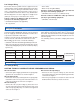
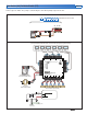
Physical Dimensions
5–1/2”
(140 mm)
5–1/2”
(140 mm)
1–1/8” (30 mm)
7/8”
(22 mm)
CL
Front View
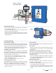
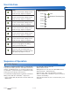
1/2” Knock-out (x 4)
315
Zone Power L
Zone Group Pump
Strip wires1/2 inch (13 mm).
Installed wires are not removable.
12-18 AWG
Ø 1/8” (3 mm)
7/8” x 1/2” (23 mm x 12 mm)
Knock-out (x 4)
1/2” x 5/8”
(12 mm x 16 mm)
Knock-out (x 4)
2–1/4”
(57 mm)
Power
Zone 1
Zone 2
Zone 3
Zone 4
Zone 5
Zone 6
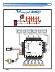
End Switch/ Zone Group Pump
C
Zone 2
WtN4 R
C
Zone 3
WtN4 R C
Zone 4
WtN4 R
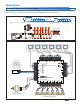
tN4 Wiring Center 315
Six Zone Valves
W tN4CtN4CX
Zone 1 Expansion
VlvC
Zone 1
VlvC
Zone 2
VlvC
Zone 3
VlvC
Zone 4
VlvC
Zone 5
VlvC
Zone 6
XC
Input Power
RR
WtN4C
Zone 5
RWtN4C
Zone 6
R
H8001B
End Switch
Use at least 167°F
(75°C) conductors
Side View Back View