
Install Instructions

6 of 12
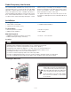
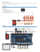
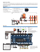
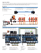
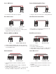
Application 305V-3
Mechanical
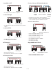
Electrical
Two Zone Valve Controls operate nine heating zones and a domestic hot water tank. When a thermostat calls for heat, the zone
valve opens. The hot water tank is heated using a pump when the tank aquastat calls for heat. The master control operates the
system pump and the boiler when there is a call for heat on either the master or member control.
Legend
A1 = DHW Tank Aquastat
B1 = Modulating Condensing Boiler
BP = Boiler Pump
PS = System Pump
P1 = Zone 1 DHW Tank Pump
T1 to T4 = WiFi Thermostat 561, 562 or 563
T5, T6 = Thermostat 518 or 519
T8 = Generic Power-Stealing Thermostat
T9 = Generic Bi-Metallic Strip Thermostat
V1 to V9 = 4-Wire Zone Valves
End switch jumper required for Zone 1 when using
a pump and Zone Valve End Switch DIP = On
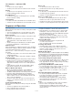
DIP Switches
Master
T-stat 1 Priority On
Exercising On
Post Purge On
DIP Switches
Member
T-stat 1 Priority Off
Exercising On
Post Purge On
Mod Boiler - depends on boiler
System Pump During Priority Off
System Pump With Member Calls On
Zone Valve End Switches On
Mod Boiler - not applicable
System Pump During Priority Off
System Pump With Member Calls Off
Zone Valve End Switches On
LN
Power
LN
System
Pump
LN LN
Power
LN
System
Pump
LN
B1
P1
A1
Expansion
PS
V1 V2 V3 V4 V5 V6
V7 V8 V9
BP
305V 305V
Away
C R Rh W
Away
C R Rh W
Away
C R Rh W
+TT
-
Away
C R Rh W
MOD
XX
tN4
T1 T2 T3 T4 T5 T6
A
DHW CRW
BOILER T-STAT 1T-STAT 2T-STAT 3
-
+
tN4
A
CRW
tN4
A
CRW
T-STAT 4
tN4
A
CRW
T-STAT 5
tN4
A
CRW
T-STAT 6 EXPANSION
tN4
A
CRW
tN4
A
BCDE
FUSE 2 FUSE 1
END
SWITCH
MOTOR
POWER
PRIORITYSYS PUMP
ROOM
RESPONSE
ZONE 1
70 80
9060
50 100
MOD MAX %
END
SWITCH
MOTOR
ZONE 2
END
SWITCH
MOTOR
ZONE 3
END
SWITCH
MOTOR
ZONE 4
END
SWITCH
MOTOR
ZONE 5
END
SWITCH
MOTOR
ZONE 6
MASTER MEMBER
OFF
OFF
OFF
T-STAT 1 PRIORITY : ON
EXERCISING : ON
POST PURGE : ON
MOD BOILER : 0-10V
SYSTEM PUMP DURING PRIORITY: ON
SYSTEM PUMP WITH MEMBER CALL: ON
ZONE VALVE END SWITCHES: ON
RESERVED
120 VAC
POWER PUMP PUMP 1
SYSTEM PRIORITY
LNLNLN
OFF
OFF
OFF
4-20 mA
Away
C R Rh W
Away
C R Rh W
Away
C R Rh W R W R W
MOD
XX
tN4
T1 T2 T3 T4 T5 T6
A
DHW CRW
BOILER T-STAT 1T-STAT 2T-STAT 3
-
+
tN4
A
CRW
tN4
A
CRW
T-STAT 4
tN4
A
CRW
T-STAT 5
tN4
A
CRW
T-STAT 6 EXPANSION
tN4
A
CRW
tN4
A
BCDE
FUSE 2 FUSE 1
END
SWITCH
MOTOR
POWER
PRIORITYSYS PUMP
ROOM
RESPONSE
ZONE 1
70 80
9060
50 100
MOD MAX %
END
SWITCH
MOTOR
ZONE 2
END
SWITCH
MOTOR
ZONE 3
END
SWITCH
MOTOR
ZONE 4
END
SWITCH
MOTOR
ZONE 5
END
SWITCH
MOTOR
ZONE 6
MASTER MEMBER
OFF
OFF
OFF
T-STAT 1 PRIORITY : ON
EXERCISING : ON
POST PURGE : ON
MOD BOILER : 0-10V
SYSTEM PUMP DURING PRIORITY: ON
SYSTEM PUMP WITH MEMBER CALL: ON
ZONE VALVE END SWITCHES: ON
RESERVED
120 VAC
POWER PUMP PUMP 1
SYSTEM PRIORITY
LNLNLN
OFF
OFF
OFF
4-20 mA
B1
PSL
L
N
NP1
V1 V2 V3 V4 V5 V6 V7 V8 V9
A1
T1
T5 T6 T7 T8 T9
T2 T3 T4