
Install Instructions


4 of 12
N
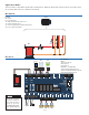
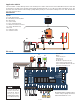
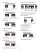
Application 303V-1
Mechanical
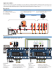
Electrical
The Zone Valve Control 303V operates three heating zones. When the thermostat calls for heat, the zone valve opens,
the system pump is turned on and the boiler is fired.
Legend
B1 = Boiler
PS = System Pump
T1 = WiFi Thermostat 561, 562 or 563
T2 = Thermostat 518 or 519
T3 = Generic Digital Power-Stealing Thermostat
V1 to V3 = 2-Wire Zone Valves
B1
PS
303V
V1 V2 V3
Away
C R Rh W
Away
C R Rh W R W
MOD
XX
tN4
T1 T2 T3 T4 T5 T6
A
DHW CRW
BOILER T-STAT 1T-STAT 2T-STAT 3
-
+
tN4
A
CRW
tN4
A
CRW
T-STAT 4
tN4
A
CRW
T-STAT 5
tN4
A
CRW
T-STAT 6 EXPANSION
tN4
A
CRW
tN4
A
BCDE
FUSE 2 FUSE 1
END
SWITCH
MOTOR
POWER
PRIORITYSYS PUMP
ROOM
RESPONSE
ZONE 1
70 80
9060
50 100
MOD MAX %
END
SWITCH
MOTOR
ZONE 2
END
SWITCH
MOTOR
ZONE 3
END
SWITCH
MOTOR
ZONE 4
END
SWITCH
MOTOR
ZONE 5
END
SWITCH
MOTOR
ZONE 6
MASTER MEMBER
OFF
OFF
OFF
T-STAT 1 PRIORITY : ON
EXERCISING : ON
POST PURGE : ON
MOD BOILER : 0-10V
SYSTEM PUMP DURING PRIORITY: ON
SYSTEM PUMP WITH MEMBER CALL: ON
ZONE VALVE END SWITCHES: ON
RESERVED
120 VAC
POWER PUMP PUMP 1
SYSTEM PRIORITY
LNLNLN
OFF
OFF
OFF
4-20 mA
B1
T1
T2 T3
PS
V1 V2 V3
L N
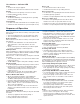
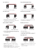
DIP Switches
Master
T-stat 1 Priority Off
Exercising On
Post Purge On
Mod Boiler - not applicable
System Pump During Priority On
System Pump With Member Calls Off
Zone Valve End Switches Off
Included 510 Ω
resistor must be
installed when
using power
stealing thermostats
(e.g. Thermostat T3)