Installation & Operation Manual D 284 Boiler Control 284 08/14 Multi-Staging Replaces: 04/14 A Flexible Solution for Commercial & Multi-Residential Heating Plants The Boiler Control 284 is designed to operate up to four boilers to accurately maintain a target water temperature. The 284 operates both condensing & non-condensing boilers that are either modulating, single stage or two stage to provide a flexible, cost effective mixed boiler plant solution with better system performance.
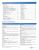
Table of Contents Sequence of Operation .....................................................2 Boiler Setup ................................................................... 2 System Setup ................................................................ 5 Boiler Plant Operation ................................................... 7 Outdoor Temperature Reset Operation ...................... 10 Setpoint Operation ......................................................
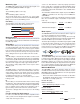
Modulating Type ---------------------------------------The MOD TYPE setting selects the analog output signal used for modulating (MOD) and EMS boiler types. 0-10 The modulating output is 0-10 V (dc). 4-20 The modulating output is 4-20 mA. The 4-20 mA output can be converted to a 0 - 135 Ω output using a 0 - 135 Ω Converter 005. Refer to the Modulating Boiler Wiring section of the Control Wiring section. Fire Delay ------------------------------------------------ can be set.
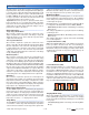
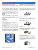
Example: A boiler requires a 1.8 V (dc) signal to fire the boiler at low fire. The boiler can be modulated to 10 V (dc) where it reaches high fire. Minimum Modulation = 10 V (dc) Control’s Output Signal Range Minimum Modulation 0 V (dc) 1.8 V x 100% = 18% 10 V 100% 88% 18% 0% 10 V (dc) Boiler’s Input Signal Range 1.
System Setup & Operation Application Mode ----------------------------------------There are five possible application modes that the 284 can be configured for including: • Outdoor Temperature Reset (RSET) • Fixed Setpoint (SETP) • Dedicated Domestic Hot Water (DDHW) • Energy Management System (EMS) • Building Automation System (BAS) Refer to the appropriate section of this brochure for a description of the each of the application modes.
Flow Monitoring ----------------------------------------- Vent Temperature Monitoring & Limiting ----------------- The control has the capability to monitor flow rate through the connection of a 4-20 mA style flow sensor. Flow is measured in either gallons per minute (gpm) or meters cubed per hour (m3/h). The units are adjustable through the FLOW UNIT setting in the Toolbox menu.
Boiler Plant Operation The 284 is able to operate up to four boilers to maintain a boiler target temperature. Proportional, Integral & Derivative (PID) logic is used in order to satisfy the boiler target temperature for all plant configurations with the exception of Dedicated Domestic Hot Water (DDHW). Proportional (P) logic is used for DDHW. For proper operation of the boilers, the 284 must be the only control that determines when a boiler is to fire.
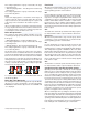
This setting is applicable for a group of at least two, two-stage condensing boilers. • STG NC (Staging Mode - Two-Stage Non-Condensing Boiler Group) This setting is applicable for a group of at least two, two-stage non-condensing boilers. Lo/Hi If the Lo/Hi staging option is selected the control stages in sequence all of the stages in a single boiler. Once all of the stages are turned on, the control then stages in sequence all of the stages of the next boiler in the rotation sequence.
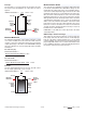
The 284 supports operation of a condensing & a non-condensing boiler group. A condensing boiler group is created when at least one boiler is selected to be condensing & a non-condensing boiler group is created when at least one boiler is selected to be non-condensing. The condensing boiler group is always sequenced on first, followed by the non-condensing boiler group.
Outdoor Temperature Reset Operation Outdoor Temperature Reset is available by setting the Application Mode in the Setup Menu to RSET. In a heating system, the rate of heat supplied to the building must equal the rate at which heat is lost. If the two rates are not equal, the building will either cool off or over heat. The rate of building heat loss depends mostly on the outdoor temperature.
Radiator (RAD) A radiator terminal unit has a large heated surface that is exposed to the room. A radiator provides heat to the room through radiant heat transfer & natural convection. Room --------------------------------------------------------------------------------------The Room setting is the desired room air temperature, according to the outdoor reset heating curve. The Room setting parallel shifts the heating curve up or down to change the target water temperature.
Setpoint Operation Setpoint operation is dependant on the application mode setting. • If the Application Mode is configured for Outdoor Temperature Reset (RSET) or Energy Management System (EMS), the control provides heat for an additional setpoint load. The control does respond to a Heat Call from a space heating system. • If the Application Mode is configured for Setpoint (SETP), the control provides heat only for the setpoint load. The control does not respond to a Heat Call for space heating.
Priority Override ------------------------------------------ Conditional Setpoint Priority --------------------------------- Priority Override applies when Setpoint Priority is set to ON. It prevents the building from cooling off too much or the possibility of a potential freeze up during setpoint priority. When set to auto, the priority time is calculated based on outdoor temperature. At or below the design outdoor temperature, 15 minutes are allowed for setpoint priority.
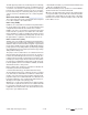
CONVERSION TABLE 2 - 10 4 - 20 mA* 2 - 10 V (dc) Boiler Target 0 0 – – – (OFF) 4 2 50°F (10.0°C) 6 3 70°F (21.0°C) 8 4 90°F (32.0°C) 10 5 110°F (43.5°C) 12 6 130°F (54.5°C) 14 7 150°F (65.5°C) 16 8 170°F (76.5°C) 18 9 190°F (88.0°C) 20 10 210°F (99.0°C) Example Range Input Offset Boiler Target = 0 - 10 V (dc) = 7 V (dc) = +5°F (3°C) = 157°F (69°C) +5°F (3°C) 162°F (72°C) The minimum & maximum settings also apply for external input operation.
IDHW Mode ----------------------------------------------- Primary Pump During IDHW --------------------------------------- The control has a IDHW MODE setting that selects whether or not indirect DHW operation is active. The control has a Primary Pump during IDHW setting that selects whether or not the primary pump is required during indirect DHW operation. OFF IDHW operation is inactive. All DHW Calls are ignored. If this mode is selected while DHW operation is underway, all DHW operation ceases.
For non-tN4 space heating, the primary pump shuts off to provide priority. If the primary pump is required to operate for IDHW, priority requires the use of an external relay to force the heating zones off. For tN4 space heating, the primary pump can operate when a Heat Call is present. If the boilers are unable to maintain the boiler target temperature, the tN4 zones are sequentially shut off using tN4 communication to provide priority.
Dedicated Domestic Hot Water (DDHW) Operation The control can operate to provide heat for a Dedicated Domestic Hot Water (DDHW) system. DDHW heating is available by setting the Application Mode in the Setup Menu to DDHW. DDHW Differential ------------------------------------------------------------A DHW Call is registered when the temperature at the DHW sensor drops the DDHW DIFF setting below the DDHW Setpoint setting.
Pump Operation Primary Pump Operation ------------------------------ A flow proof call can be provided in two ways: The control includes two primary pump outputs with capability for sequencing. There is pump enable setting for each primary pump in the Setup menu. When both primary pumps are set to Auto, primary pump sequencing is activated. Primary pump 1 & 2 are operated in stand-by mode when pump sequencing is activated. The running times of the primary pumps are logged in the Monitor Menu.
Stand-by Pump Operation Failed ON Flow Proof Delay ---------------------------------------The control waits a period of time to receive a flow proof call from the time the primary pump turns on. If the control does not receive a flow proof call within that period of time, the primary pump turns off & the stand-by primary pump (if active) turns on. The control then waits that period of time again for the stand-by primary pump to prove flow. If flow is not proven, the stand-by pump turns off.
Combustion Air (C.A.) Damper & DHW Recirculation Pump Settings Auxiliary Relay ------------------------------------------ Combustion Air Proof Delay ---------------------------------------- The control includes an auxiliary relay that can be used either for a combustion / venting device or a DHW recirculation pump. Selection is made through the AUX RELAY item in the Setup menu. Off is also available if there is no Auxiliary device.
Day Saturday Sunday Monday Tuesday Wednesday Thursday Friday 24 Hour Schedule Type 5-2 5-11 • • • • • Events / Day Event Occupied 1 UnOccupied 1 4 events per day Occupied 2 UnOccupied 2 or Occupied 2 events per day Unoccupied • Events / Day The events / day can be either 4 or 2. An event is a time at which the control changes the target temperature. The event time can be set to the nearest 10 minutes. If you wish to have the thermostat skip the event, enter “--:--“ as the time.
Important Safety Information It is your responsibility to ensure that this control is safely installed according to all applicable codes and standards. tekmar is not responsible for damages resulting from improper installation and/or maintenance. To avoid serious personal injury and damage to the equipment: • Read Manual and all product labels BEFORE using the equipment. Do not use unless you know the safe and proper operation of this equipment. • Keep this Manual available for easy access by all users.
Control Wiring This section explains how to wire individual devices to the Boiler Control 284. For step by step wiring refer to the terminal number on the right of the page. • Before wiring, ensure all power is turned off & take all necessary precautions. • Install the supplied wiring compartment barriers by sliding them into the grooves provided to isolate the low & high voltage wiring. • Strip all wiring to a length of 3/8 in. or 10 mm for all terminals.
Wiring an Indirect DHW Pump Terminals 85, 86 An indirect DHW pump requiring up to 230 V (ac) 5 A, 1/3 hp can be switched through the IDHW Pump terminals. • Connect the line wire (L) to terminal 85. • Connect a wire from terminal 86 to the pump L. • Connect a wire from the pump N back to the power source neutral. • Ensure grounds are connected in the pump & control wiring chambers. Boiler Control 284 85 86 IDHW Pump L N G G N L Ground Wiring a Combustion Air (C.A.
Wiring a Heat Call Terminals 5, 6 The 284 requires a switched external heat call to operate the boiler plant unless calls for heat are generated through a tekmarNet ® device, EMS, BACnet® or Modbus® connection. The heat call can be volt free or up to 24 V (ac). • Connect the Heat Call terminals 5 & 6 to a switched heat demand. • Typical heat calls are from a zone relay box or thermostat. • A permanent heat call can be created by installing a jumper wire between terminals 5 & 6.
Modulating Boiler Wiring Terminals 51 to 72 For modulating boilers that do not require an enable: • The 284 provides either a 4-20 mA or a 0-10 V (dc) output to each boiler. • Polarity is important. • Connect the Mod + terminals from boilers 1, 2, 3 and 4 to the 284 terminals 51, 57, 63 and 69, respectively. • Connect the Mod - terminals from boilers 1, 2, 3 and 4 to the 284 terminals 52, 58, 64 and 70, respectively.
Wiring the Outdoor Sensor (tekmar 070) Terminals 17, 19 • Connect 18 AWG or similar wire to the two terminals provided in the enclosure & run the wires from the sensor to the control. Do not run the wires parallel to telephone or power cables. If the sensor wires are located in an area with strong sources of electromagnetic interference (EMI), shielded cable or twisted pair should be used or the wires can be run in a grounded metal conduit.
Wiring a Boiler Inlet Sensor (tekmar 082) Terminals 24, 25 A single boiler inlet sensor measures the water temperature entering the boilers. • Connect one wire from the boiler inlet sensor to the Boil In terminal 24. • Connect the second wire to the Com terminal 25. Vent Boil Com In 23 24 25 No Power Wiring a Boiler Supply Sensor (tekmar 082) Terminals 18, 19 A boiler supply sensor measures the temperature of water coming from the boiler plant.
Wiring a Pressure Sensor Terminals 13 to 15 An analog pressure sensor can be connected to the 284 to provide water pressure monitoring. The control supports a V (dc) style pressure sensor with a signal range of 0.5 to 4.5 V (dc). Examples of compatible aftermarket pressure sensors include the Honeywell PX2 (AA) series and the Measurement Specialties 7100 series. • Connect one wire from the power supply (+5 VDC) on the pressure sensor to the 5V dc Out terminal 13.
Wiring the tekmarNet® Devices tN4 Boiler Bus b Terminals 32 - 33 Terminals 32 & 33 provide communication for tN4 devices on the tN4 Boiler Bus b. Connect terminals 32 (tN4) & 33 (C0) to the corresponding terminals on the tN4 devices that are to be connected. The connection is polarity sensitive. Ensure that terminal 32 (tN4) is connected to the tN4 terminal on the tN4 device & that terminal 33 (C0) is connected to the C terminal on the tN4 device.
Testing the Control Wiring Testing the Power Terminals 83 & 84 If the control display does not turn on, check the Power In L & N terminals (83 & 84) using an electrical multimeter. The voltage should measure between 103.5 to 126.5 V (ac). User Test (HAND) Manual Override Button The User Test (HAND mode) is one of the Manual Override modes of the control. Refer to the Hand mode for a description of the steps that are included to operate the outputs.
Testing the Heat Call Terminals 5 & 6 Set the Application Mode to RSET. Remove all wires from the Heat Call terminals (5 & 6). The control display should show no Heat Call. Reconnect wires. Then apply either a short circuit or 24 V (ac) over the Heat Call terminals. The control should now show a Heat Call. Testing the DHW Call Terminals 7 & 8 Set the Application Mode to either RSET, SETP or EMS. Remove all wires from the DHW Call terminals (7 & 8). The control display should show no DHW Call.
Control Settings Access Level The access level restricts the number of menus & items that can be accessed by the user. The Access Level setting is found in the Toolbox menu. Select the appropriate access level for the people who work with the control on a regular basis. There are three Access Level settings: • User (USER): Select this access level to limit the number of items available to the end user. • Installer (INST): Select this access level to limit some of the items available to the installer.
User Interface Display Menu Field Item Field Number Field Displays the name of the selected item Displays the current value of the selected item Displays the current menu Buttons Use for navigation & adjustment Status Fields Displays the current status of the control’s inputs, outputs & operation.
Navigating The Display The menu items of the 284 are described in detail in the following pages. The number of available items changes depending on the control configuration. To find out what other settings affect the display of an item, refer to the menu descriptions.
View Menu (2 of 2) Item Field Range Description ---, -22 to 266°F (-30.0 to 130.0°C) DEDICATED DHW Current dedicated DHW tank temperature as measured by the DHW sensor. “----” is displayed if there is a sensor fault. This item is only available if Application Mode is set to DDHW. Access: User ---, -22 to 266°F (-30.0 to 130.0°C) Access: ADV -22 to 266°F (-12.0 to 148.0°C) Access: ADV ---, -40 to 500°F (-40.0 to 260.
Setup Menu (1 of 6) Setup Menu items are used for system specific configuration. Item Field Range RSET, SETP, DDHW, EMS, BAS Default = RSET Access: INST Description APPLICATION MODE RSET = Outdoor Temperature Reset SETP = Setpoint Heating DDHW = Dedicated DHW Heating EMS = Energy Management System BAS = Building Automation System 35 to 100°F (2.0 to 38.0°C) ROOM OCCUPIED Default = 70°F (21.0°C) The desired room air temperature during the occupied periods.
Setup Menu (2 of 6) Item Field Range Description BOILER MINIMUM The minimum allowed boiler target temperature used for the non-condensing boiler group. Check the boiler manufacturer’s manual for recommended minimum Default: 140°F (60.0°C) boiler supply temperatures. This item is only available if there is at least one boiler set to auto Access: ADV (Boiler Enable = AUTO) & non-condensing (Boiler Condense = NO). OFF, 60 to 180°F (OFF, 15.5 to 82.0°C) 90 to 225°F, OFF (32.0 to 107.
Setup Menu (3 of 6) Item Field Range OFF, 0:10 to 3:00 min Default: 1:00 min Access: ADV 150 to 350°F, OFF (65.5 to 177.
Setup Menu (4 of 6) Item Field Range OFF or ON Default: OFF Access: ADV AUTO, 5 to 30 min Default: AUTO Access: ADV OFF or ON Default: OFF Access: ADV NEAR or Boil Default: Boil Access: ADV OFF or ON Default: OFF Access: ADV Description FIXED LAST Selects whether or not the last boiler is to be excluded from the rotation sequence. If set to ON, boiler 4 is always the last to fire.
Setup Menu (5 of 6) Item Field Range Description OFF or ON INDIRECT DHW PRIORITY Selects whether indirect DHW priority is active or not. This item is only available when Application Mode is set to RSET or EMS & Indirect DHW Mode is set to ON.
Setup Menu (6 of 6) Item Field Range 2 to 10°F (1.0 to 5.5°C) Default: 5°F (3.0°C) Access: ADV OFF, AUTO, 0:20 to 4:00 hrs Default: OFF Access: ADV Description DEDICATED DHW DIFFERENTIAL The temperature differential of the dedicated DHW tank from the DDHW SETPOINT settings. This item is only available when Application Mode is set to DDHW. PRIORITY OVERRIDE The amount of time priority is given for indirect DHW or setpoint operation before space heating resumes.
Source # Menu (1 of 2) There is a different Source Menu for each of the 4 boilers that the 284 can operate. Settings can vary for each boiler if desired. OFF or AUTO Default: AUTO for Boil1 OFF for Boiler 2-4 BOILER ENABLE Selects whether the boiler is operational or not.
Source # Menu (2 of 2) 10 to 230 sec Default: 30 sec Access: ADV 0 to 100% Default: 0% Access: ADV 0 to 50% Default: 0% Access: ADV 50 to 100% Default: 100% Access: ADV 0.5 to 10.0 Default: 1.0 Access: ADV 50 to 210°F, OFF (10.0 to 99.0°C) Default: 50°F Access: ADV 50 to 210°F, OFF (10.0 to 99.0°C) Default: 210°F Access: ADV MOTOR SPEED The amount of time required for the modulating actuating motor to fully open the gas valve or operate the blower from a stopped position to full speed.
BAS Menu (1 of 2) Configure Modbus® & BACnet ® options. Item Field Range OFF or ON Default: OFF Access: ADV BACn, MODB Default: BACn Access: ADV 1 to 247 Default: 1 Access: ADV RTU or ASCI Default: RTU Access: ADV 2400, 9600, 19K2, 57K6, 115K Default: 19K2 Access: ADV NONE, EVEN, ODD Default: EVEN Access: ADV Description BAS MONITOR Selects whether or not BAS monitor mode is to be used. Monitor mode allows for read / write capability of select menu items.
BAS Menu (2 of 2) Item Field Range Description BACNET GATEWAY 0 to 255, 0 to 255, 0 to Sets the Gateway address on the BACnet® network. The address is set using four number sets displayed in the source output fields. Touch the ‘Next Item’ button to 255, 1 to 254 view & adjust each number set. Touch the ‘Next Item’ button to view & adjust each Default: 192,168,0,1 number set. Access: ADV This item is only available when BAS Type is set to BACn & BACn DHCP is set to OFF.
Monitor # Menu (1 of 1) Monitor (#) items are repeated for each available boiler. Item Field Range 0 to 65535 hours Access: ADV 0 to 65535 hours Access: ADV 0 to 65535 Access: ADV -22 to 266°F (-30.0 to 130.0°C) Access: ADV -22 to 266°F (-30.0 to 130.0°C) Access: ADV -22 to 266°F (-12.0 to 148.0°C) Access: ADV A Watts Water Technologies Company Description BURNER RUN TIME The total running time of the boiler since this item was last cleared. Press & hold the ‘CLEAR’ button while viewing to reset.
Monitor Menu (1 of 2) This Monitor Menu displays items that are not specific to one boiler. Item Field Range 0 to 65535 Therms Access: ADV 0 to 65535 hours Access: ADV 0 to 65535 hours Access: ADV 0 to 65535 hours Access: ADV -22 to 266°F (-30.0 to 130.0°C) Access: ADV -22 to 266°F (-30.0 to 130.0°C) Access: ADV -22 to 266°F (-30 to 130°C) Access: ADV -22 to 266°F (-30.0 to 130.0°C) Access: ADV -22 to 266°F (-12.0 to 148.
Monitor Menu (2 of 2) Item Field Range Description -22 to 266°F BOILER INLET HIGH Records the highest boiler inlet temperature since this item was last cleared. Press & hold the ‘CLEAR’ button while viewing to reset. This item is only available when a boiler inlet sensor is connected. (-30.0 to 130.0°C) Access: ADV -22 to 266°F (-30.0 to 130.0°C) Access: ADV -76 to 149°F (-60.0 to 65.0°C) Access: ADV -76 to 149°F (-60.0 to 65.0°C) Access: ADV -22 to 266°F (-30.0 to 130.
Time Menu (1 of 1) The Time menu sets the time & date. The Setback / Off switch setting must be in the Setback position in order to have access to the Time menu. Set minutes. Set hours, then select AM or PM. For a 24 hr clock, AM / PM is not displayed. Set date. Set year. Turn daylight savings time ON if an automatic time change is required. Select 12 or 24 hr clock. A Watts Water Technologies Company 50 of 60 Set month. Select On or Off.
Schedule Menu (1 of 1) The 284 can follow an internal schedule or an available schedule on a tekmarNet® network. Four heating schedules can be present on one network. The number of available schedule times depends on selections made for the Heat Schedule, Schedule Type & Events / Day settings.
Toolbox Menu (1 of 2) Item Field Range Error Display Access: --USER, INST, ADV Default: INST Access: USER OFF, SEL, DONE Default: OFF Access: ADV 284, Software Version Access: USER Description ERROR If an error is present, it will be displayed as the first item in the toolbox menu. Additional troubleshooting information scrolls on the display. For more information about error messages, refer to the Error Messages section of this document. ACCESS LEVEL The access level of the control.
Toolbox Menu (2 of 2) Item Field Range Description 1 to 24 BOILER BUS 3 DEVICES Displays the number of tN4 devices connected to the Boiler Bus 3 terminals, tN4 & C3 (38 & 39). Access: INST The error date & the type of error alternate on the screen ERROR HISTORY 1-5 Displays a history of any past errors that have occurred on the system. Will automatically clear after 30 days. To manually clear, press ‘CLEAR’ while viewing the error until CLR is displayed.
Manual Override Commissioning, testing & troubleshooting features of the 284 are accessed by holding the Manual Override button for 3 seconds. Once an item is selected in this menu, there is a 3 second delay before the feature activates. The Manual Override has five different modes including: Automatic (AUTO) --------------------------------------The normal operating mode for the control is automatic. The control operates based on the settings, calls & current conditions.
Selecting a Manual Override Mode Press & hold for 3 seconds Once an item is selected in this menu, there is a 3 second delay before the feature activates. Manual Override Item Field Range Description AUTO, OFF, HAND, MAX, PURG MANUAL OVERRIDE Select which mode of manual override to activate. 1hr to 72hr TIMEOUT Set the timeout used for the Hand & Maximum Heat manual overrides. This item is only available if Manual Override is set to either HAND or MAX.
Troubleshooting It is recommended to complete all wiring to ensure trouble free operation. Should an error occur, simply follow these steps: 1. Find: If the Boiler Control 284 flashes on the screen, it is indicating a problem on the system. 2. Identify: Press & hold the Home button for 3 seconds to view the available menus. Tap the NEXT ITEM button to locate the Toolbox Menu & press ENTER to view the toolbox menu items. The Error code should appear as the first item.
Error Messages (2 of 3) Error Message Description Troubleshooting Tips BOILER (#) OUTLET SENSOR MAXIMUM EXCEEDED The boiler outlet (#) temperature exceeded the Maximum Outlet temperature. As a result, the control stops operation for the associated boiler. The error message self clears once the error condition is cleared. BOILER (#) OUTLET TEMP EXCEEDS MAX OUT SETTING BOILER INLET SENSOR ERROR OPEN or SHRT displays on the screen.
Error Messages (3 of 3) Error Message Description Troubleshooting Tips tekmarNet DEVICE LOST Communication is lost to a tN4 device on one of the four Boiler Buses (b, 1, 2, 3). The number shown is the address of the lost device. The display on the lost device displays Bus Boil Opn. Ensure that there is power to the lost device. Trace the wires from the control to the lost device looking for loose or damaged wires. The error message self clears when the error condition is corrected.
Notes A Watts Water Technologies Company 59 of 60 © 2014 284_D - 08/14
Technical Data Boiler Control 284 Four tN4, BAS, Four Boiler, DHW & Setpoint Literature Control Packaged weight Dimensions Enclosure Approvals Ambient conditions Power supply Primary Pump relays Boiler Pump / Valve & IDHW Pump relays Boiler Stage, Auxiliary & Alert relays Modulating outputs Calls Sensors –Included –Optional Warranty 284_A, 284_B, 284_C, 284_D Microprocessor control. This is not a safety (limit) control 5.5 lb.