
Application Brochure

3 of 4 © 2007 A 279 - 12/07
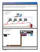
Electrical
Application A 279-3
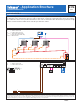
System Description: The Steam System includes two on/off steam valves, each of which are operated by a Steam
Control 279. The steam can be supplied from either a steam boiler or a district steam system. The on time of the valve is
based on outdoor temperature, condensate return temperatures, control settings, and indoor temperature settings. The
condensate return sensor provides information to the control to determine when the boiler has produced enough steam
to reach the furthest radiator to start the percent on time. The indoor sensor provides indoor temperature feedback to
prevent over and under heating of the building.
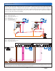
Mechanical
Concept Drawing: This is only a concept drawing, not an engineered drawing. It is not intended to describe a complete system, nor any particular system. It is up to the
system designer to determine the necessary components for and configuration of the particular system being designed, including additional equipment, isolation relays
(for loads greater than the control’s specified output ratings), and any safety devices which in the judgement of the designer are appropriate, in order to properly size,
configure and design that system and to ensure compliance with building and safety code requirements.
S2S4
115 V (ac)
24 V (ac)
Class II
Transformer
V1
F1
S5
A1
A2
T1
Zone 1
V2
F2
S6
A3
A4
T2
Zone 2
279
S1S3
115 V (ac)
24 V (ac)
Class II
Transformer
279
S5
S1
S3
S6
S2
V2
S4
14
Sen
13
S1
12
S2
11
Sen
10
Sen
9
Sen
15
Sen
16
Sen
Do not apply power
279
N
52
Power
L
634 7
Boiler Com Com
DHW
Indr Indr Com Cdn Out
8
Alert 2Alert 1
High Low
1
14
Sen
13
S1
12
S2
11
Sen
10
Sen
9
Sen
15
Sen
16
Sen
Do not apply power
279
N
52
Power
L
634 7
Boiler Com Com
DHW
Indr Indr Com Cdn Out
8
Alert 2Alert 1
High Low
1
24V(ac)
N
R
C
115 V (ac)
Class II
Transformer
L
M
V1
M
S1, S2 = Outdoor Sensors 070
S3, S4 = Indoor Sensors 076, 077 or 084
S5, S6 = Condensate Sensors 071
A1...A4 = Main Air Vents
F1, F2 = Float and Thermostatic Traps
V1, V2 = On/Off Steam Valves
T1, T2 = Thermostatic Steam Traps
S1, S2 = Outdoor Sensors 070
S3, S4 = Indoor Sensors 076, 077 or 084
S5, S6 = Condensate Sensors 071