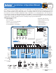
D 275 Installation & Operation Manual 01/12 Boiler Control 275 Multi-Staging Replaces:03/09 The Boiler Control 275 is designed to stage up to four condensing or non-condensing, modulating or on-off boilers using P.I.D. staging to accurately maintain temperature. The control supports hybrid boiler plants that contain both condensing and non-condensing boiler groups.
How to Use the Data Brochure This brochure is organized into three main sections. The Control Settings section of this brochure describes the various items that are adjusted and displayed by the control. The control functions of each adjustable item are described in the Sequence of Operation. They are: 1) Sequence of Operation, 2) Installation, 3) Control Settings and 4) Testing and Troubleshooting. Table of Contents User Interface ...............................................................
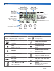
Display Number Field Item Field Displays the current value of the selected item Displays the current item selected Menu Field Displays the current menu Status Field Displays the current status of the control’s inputs, outputs and operation Buttons Selects Menus, Items and adjusts settings Menu Item Symbol Description PRIMARY PUMP Displays when primary pump 1 or primary pump 2 is in operation BOILER PUMP Displays when the boiler pump 1, 2, 3, or 4 are operating BOILER Displays which modulating out
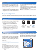
Access Level The access level restricts the number of Menus, Items, and Adjustments that can be accessed by the user. The Access Level setting is found in the Miscellaneous (MISC) Menu. Select the appropriate access level for the people who work with the control on a regular basis. There are three Access Level Settings: • User (USER): Select this access level for building supervisors and other non-technical staff to prevent unauthorized access to installer and advanced level settings.
Terminal Unit Setting in Adjust Menu Select the appropriate terminal unit in the adjust menu. This will change the shape of the characterized heating curve to better match the heat transfer properties of that specific terminal unit. Hydronic Radiant Floor (HRF1) A heavy or high mass, hydronic radiant floor system. This type of a hydronic radiant floor is embedded in either a thick concrete or gypsum pour. This heating system has a large thermal mass and is slow acting.
Outdoor Design Setting in Adjust Menu Boiler Design Setting in Adjust Menu The outdoor design temperature is typically the coldest outdoor air temperature of the year. This temperature is used when doing the heat loss calculations for the building and is used to size the heating system equipment. If a cold outdoor design temperature is selected, the supply water temperature rises gradually as the outdoor temperature drops.
Stage Delay Setting in Adjust Menu The Stage Delay is the minimum time delay between the firing of each stage. After this delay has expired the control can fire the next stage if it is required. This setting can be adjusted manually or set to an automatic setting. When the automatic setting is used, the control determines the best stage delay based on the operation of the system. Boiler Relay Setting in Adjust Menu (per boiler) The 275 provides a dry contact for either burner ignition or boiler pump.
Modulating Boilers Section D The 275 can operate up to four modulating boilers. The control also provides dry contacts for either burner ignition or boiler pump. Selection is made through Boiler Relay setting in the Adjust menu. Once a boiler is required to operate, the control outputs an analog signal corresponding to the Start Modulation setting and then turns on the boiler relay. Once the Fire Delay time has elapsed, the modulating output is adjusted to the Minimum Modulation setting.
Boiler Minimum Modulation Setting in Adjust Menu (per boiler) The Minimum Modulation setting is the lowest modulation output to obtain low fire. The Minimum Modulation setting is typically based on the turndown ratio of the boiler. The control adjusts the modulating output signal from Minimum Modulation to 0% after the burner turns off and boiler operation is not required. For boilers with electronic operators, the boiler’s input signal range may not match the output signal range of the 275 control.
On / Off Boilers Section E The 275 can operate up to four modulating or on/off boilers in any combination. Each boiler stage has a Boiler Mode setting in the the Adjust menu that allows the selection of either modulating (Mod) or on/off (OnOF). By selecting a boiler stage to on/off, the 275 then uses sequential boiler staging, the stage relay is set to operate a burner, and settings related to modulation are removed from the boiler settings.
Domestic Hot Water Operation Section I DHW operation is only available when the Pump Sequencer DIP Switch is set to Off. DHW Demand DHW Demands come from one of three sources: an external aquastat, a DHW tank sensor, or a tN4 Setpoint Control. Once the control detects a DHW Demand, the DHW Demand segment is displayed in the LCD. If an External Powered DHW Demand is applied while the DHW sensor is enabled in the 275, an error message is generated and both demands are ignored.
Mode 1 - DHW in Parallel with No Priority When a valid DHW Demand is present, the DHW relay (terminal 23) turns on. The primary pump can operate when a Boiler Demand is present. It is assumed that the DHW pump will provide adequate flow through the heat exchanger and the boiler. Heating zones are unaffected by DHW operation. Mode 4 - DHW in Primary/Secondary with Priority When a valid DHW Demand is present, the DHW relay (terminal 23) and Primary Pump relay (terminal 24) turn on.
Mode 6 – Dedicated DHW When a valid DHW Demand is present from the DHW Sensor, the primary pump relay turns on. The DHW Relay in this mode is used as the DHW recirculation pump and operates continuously in the Occupied period and cycles with the primary pump in the UnOccupied period. The boiler plant is sequenced based only on the DHW Sensor.
Setpoint Operation Section J Setpoint operation is only available when DHW Mode is set to Off. The control can operate to satisfy the requirements of a setpoint load in addition to a space heating load. A setpoint load overrides the current outdoor reset temperature in order to provide heat to the setpoint load. Setpoint Demand Setpoint Demands come from one of two sources: a Powered Setpoint Demand, or a tN4 Setpoint Control.
Mode 3 - Setpoint in Primary/Secondary with No Priority Whenever a Setpoint Demand is present, the primary pump is turned on and the boilers are operated to maintain the setpoint target. Automatic Priority Override 2 hours Mode = 3 Setpoint 15 mins Primary Pump 70°F (21°C) Design Temperature Conditional DHW Priority Mode 4 - Setpoint in Primary/Secondary with Priority Whenever a Setpoint Demand is present, the primary pump is turned on and the boilers are operated to maintain the setpoint target.
Energy Management System (EMS) Section K The control can accept an external DC signal from an Energy Management System (EMS) in place of the outdoor sensor. The control converts the DC signal into the appropriate boiler target temperature between 50°F (10°C) and 210°F (99°C) based on the EMS Input Signal and Offset settings. To use the external input signal, the EMS / Demands DIP switch must be set to EMS.
Pump Operation Section L Primary Pump Operation Stand-by Operation The control includes two primary pump outputs with capability for sequencing. Primary pump sequencing is activated through a DIP switch. Only primary pump 1 is operated when pump sequencing is turned off, while primary pumps 1 and 2 are operated in stand-by mode when pump sequencing is turned on. The control only operates one primary pump at a time. A flow proof device can be used to detect when stand-by pump operation is required.
Flow Proof Demand Test The control includes a flow proof demand test in order to determine if the flow/pressure device has failed. A flow proof failure is detected if a flow proof is present after the pumps have been shut off for more than four minutes. This can occur if the flow proof device sticks in the on position even when flow has stopped in the system. A proof demand error will latch when this condition exists.
Combustion Air Proof Demand Test The control includes a C.A. proof demand test in order to determine if the proving device has failed. If the C.A. damper contacts are opened, the flow proof demand should not be present after 4 minutes. If the flow proof demand remains, the control will display an error message. Setting the Schedule Section N To provide greater energy savings, you can operate the control on a programmable schedule.
Time Clock Section O The control will exercise the Combustion Air Damper, all pumps, and tN4 zones (zone valves and zone pumps) for 10 seconds every three days of inactivity to prevent seizure. To enable exercising, switch the Exercise / Off DIP to the Exercise position. The control has a built-in time clock to allow the control to operate on a schedule. A battery-less backup allows the control to keep time for up to 4 hours without power.
Zone Load Shedding (tN4) Indoor Temperature Feedback (tN4) Zone load shedding helps protect non-condensing boilers from sustained flue gas condensation damage. Zone load shedding starts when the boiler supply temperature is below the boiler minimum setting and all boilers are operating at 100% output. Zones are shut off in order of their tN4 address. Indoor feedback applies when the 275 is connected to a tN4 Thermostat network operating on a boiler bus.
Installation Caution Improper installation and operation of this control could result in damage to the equipment and possibly even personal injury or death. It is your responsibility to ensure that this control is safely installed according to all applicable codes and standards. This electronic control is not intended for uses as a primary limit control. Other controls that are intended and certified as safety limits must be placed into the control circuit. Do not attempt to service the control.
Step Four — Electrical Connections to the Control General The installer should test to confirm that no voltage is present at any of the wires. Push the control into the base and slide it down until it snaps firmly into place. Terminals 25 - 31 Powered Input Connections 115 V (ac) Power Connect the 115 V (ac) power supply to the Power L and Power N terminals (25 and 26). This connection provides power to the microprocessor and display of the control.
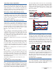
Terminals 1 - 6 Non-Powered Input Connections tN4 Terminals 1 and 2 provide a tN4 connection for tN4 devices on the tN4 bus. Connect terminals 1 (tN4) and 2 (Com) to the corresponding terminals on the tN4 devices that are to be connected. tN4 Device 1 2 tN4 Com - tN4 Com Note: The connection is polarity sensitive. Ensure that terminal 1 (tN4) is connected to the tN4 terminal on the tN4 device and that terminal 2 (C) is connect to the C terminal on the tN4 device.
Terminals 7 – 22 Non-Powered Output Connections Wiring the Modulating Boiler Outputs The control provides a 0-10 V (dc) modulating output to four modulating boilers. 7 8 9 10 11 12 Mod1 Mod2 Mod3 Mod4 + + + + • Polarity is important. + + Wiring the T-T (RELAY TYPE = Boiler - Modulating Boiler 4 + Modulating Boiler 3 - Note: Some modulating boilers may also require an on / off signal in addition to the modulating signal. See terminals 13 to 20.
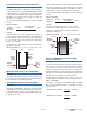
Step Five — Testing the Wiring General The following tests are to be performed using standard testing practices and procedures and should only be carried out by properly trained and experienced persons. ### 2 3 Com Out + A good quality electrical test meter, capable of reading from at least 0-300 V (ac), 0-30 V (dc), 0-2,000,000 Ohms, and testing for continuity is essential to properly test the wiring and sensors.
Terminals 13 – 20 Testing Relay 1 – 4 1. Shut off power to the control and the boiler circuit or boiler pump circuit. 2. Remove the bottom cover from the control. Disconnect the wiring from the Relay contacts (terminals 13 – 20). 3. Apply power to the control and press the Test button. 4. Use an electrical test meter and check for continuity between terminals 13 - 14, 15 - 16, 17 - 18, and 19 - 20.
Control Settings Cleaning the Control The control’s exterior can be cleaned using a damp cloth. Moisten the cloth with water and wring out prior to wiping control. Do not use solvents or cleaning solutions. DIP Switch Settings Set the DIP switch settings prior to making adjustments to the control through the user interface. Setting the DIP switches determines which menu items are displayed in the user interface.
Rotate / Off Fixed Last / Off Use the Rotate / Off DIP switch to enable the Equal Run Time Rotation feature. This feature Changes the firing order of the boilers in order to maintain a similar amount of running time on each boiler. If set to Off, the firing sequence if fixed starting with boiler 1 to boiler 4. Use the Fixed Last / Off DIP switch to exclude the last boiler in the rotation sequence. This DIP is only active when the Rotate / Off DIP is set to Rotate.
Display Menus View Menu (1 of 2) The View menu items display the current operating temperatures and status information of the system. Item Field Range Access -76 to 149°F (-60.0 to 65.0°C) USER INST ADV -22 to 266°F (-30.0 to 130.0°C) USER INST ADV VIEW Description OUTDOOR Current outdoor air temperature as measured by the outdoor sensor. Note: This item is only available when the EMS/ Demands DIP is set to Demands. VIEW VIEW ---, 35 to 230°F (---, 1.5 to 110.
View Menu (2 of 2) Item Field Range Access VIEW 0 to 100 % or ADV 1 to 4 2 VIEW 0 to 100% or ADV 1 to 4 3 VIEW 0 to 100% or ADV 1 to 4 4 VIEW VIEW MENU hr 0 to 9999 hours ADV BOILER 1 RUNNING TIME SECTION C The total running time of boiler 1 since this item was last cleared. To clear this item, press the up and down buttons together while viewing this item. Note: This item is only available when boiler 1 is set to Auto.
Adjust Menu (1 of 7) The Adjust Menu items are the programmable settings used to operate the mechanical equipment. Item Field Range 35 to 100°F (2.0 to 38.0°C) ADJUST Occ Default = 70°F (21.0°C) 35 to 100°F (2.0 to 38.0°C) ADJUST UnOcc Default = 70°F (21.0°C) ADJUST 0-10, 2-10 ADJUST MENU Default = 0-10 -10 to 10°F (-5.6 to 5.
Adjust Menu (2 of 7) Item Field Range Access Description ADV BOILER 2 MODE SECTION D, E, F Select whether boiler 2 is modulating (Mod) or on-off (OnOF). If the BTC I / Off DIP switch is set to BTC I, then select the number of boiler stages for boiler 2. INST ADV BOILER 3 SECTION C Selects whether boiler 3 is operational or not. CP1 copies the settings of boiler 1 to boiler 3 and selects boiler 3 to be operational.
Adjust Menu (3 of 7) Item Field Range OFF or On Default = OFF OFF, 80 to 180°F (OFF, 26.5 to 82.0°C) ADJUST Access Description ADV SECTION H CONDENSING LEAD Select whether or not the lead group of boilers are condensing or not. When set to On, the boiler minimum setting is not applied to the lead group of boilers. Note: Only available when Fixed Lead / Off DIP switch is set to Fixed Lead, or when Fixed Last / Off DIP switch is set to Fixed Last.
Adjust Menu (4 of 7) Item Field ADJUST Range min 0:10 to 3:00 minutes Access Description ADV SECTION M DAMPER DELAY The time delay for the boiler to operate once the combustion air damper relay closes. Note: Only available when Relay is set to Damper and Proof Demand is set to Combustion Air (CA). ADV SECTION D MODULATION MODE Selects either sequential or parallel modulation. Note: This item is only available when the BTC I / Off DIP is set to Off and DHW Mode is set to 1 to 5.
Adjust Menu (5 of 7) Item Field Range 10 to 230 seconds ADJUST Default = 30 seconds 1 ADJUST 0 to 100% Default = 0% Access Description ADV BOILER 1 MOTOR SPEED SECTION D The amount of time required for the modulating actuating motor to fully open the gas valve or operate the fan speed from a stopped position to full speed. Note: This item is only available when Boiler 1 is set to Auto and Boiler 1 Mode is set to Mod.
Adjust Menu (6 of 7) Item Field ADJUST Occ ADJUST UnOcc Range OFF, 70 to 190°F (OFF, 21.0 to 87.5°C) Default = 140°F (60.0°C) OFF, 70 to 190°F (OFF, 21.0 to 87.5°C) Access Description INST ADV SECTION I DHW OCCUPIED The temperature of the DHW tank during the wake and occupied periods. Note: This item is only available when DHW Mode is 1, 2, 3 or 4, the DHW Sensor is set to On, and the Pump Sequencer / Off DIP is Off.
Adjust Menu (7 of 7) Item Field Range ADJUST OFF, On Default = OFF UnOcc ADJUST OFF, On Default = On OFF, AUTO, 0:20 to 4:00 hours ADJUST Access Description ADV SETPOINT UNOCCUPIED SECTION J Selects whether the control should respond to Setpoint demands while in unoccupied mode. Note: This item is only available when DHW Mode is set to Off, and Setback / Off DIP is set to On. ADV ZONE LOAD SHEDDING SECTION R Selects whether Zone Load Shedding is active or not.
Time Menu (1 of 2) Note: The Setback / Off switch setting must be in the Setback position in order to have access to the TIME menu. The Time menu items set the time clock, day and date. Item Field Range TIME Default = MONDAY 12:00 AM AM TIME Access Description USER CURRENT TIME AND DAY SECTION O Displays the current time and day of the week. The time and date flash if the time is not set.
Time Menu (2 of 2) Item Field Range Access TIME MENU TIME Description YEAR Set the current year. SECTION O 2000 ... 2255 INST Default = 2005 ADV Note: This item is only available when Daylight Savings Time is set to Mode 1 or 2. 12 hr OR 24 hr INST Default = 12 hr ADV MODE SECTION O Select whether time should be displayed using a 12 or a 24 hour clock. TIME After the last item, the control returns to the first item in the menu.
Schedule Menu (2 of 3) Item Field SCHD Range AM Wake UnOcc Sleep – –:– – to 11:50 PM or – –:– – to 23:50 Wake Default = 6:00 AM UnOccupied Default = 8:00 AM Occupied Default = 6:00 PM Sleep Default = 10:00 PM SCHD AM Wake UnOcc Sleep – –:– – to 11:50 PM or – –:– – to 23:50 Access USER INST ADV USER SCHEDULE MENU INST Wake Default = 6:00 AM UnOccupied Default = 8:00 AM Occupied Default = 6:00 PM Sleep Default = 10:00 PM SCHD AM Wake UnOcc Sleep – –:– – to 11:50 PM or – –:– – to
Schedule Menu (3 of 3) Item Field SCHD Range AM Wake UnOcc Sleep Wake Default = 6:00 AM UnOccupied Default = 8:00 AM Occupied Default = 6:00 PM Sleep Default = 10:00 PM SCHD AM Wake UnOcc Sleep SCHEDULE MENU – –:– – to 11:50 PM or – –:– – to 23:50 – –:– – to 11:50 PM or – –:– – to 23:50 Wake Default = 6:00 AM UnOccupied Default = 8:00 AM Occupied Default = 6:00 PM Sleep Default = 10:00 PM SCHD AM Wake UnOcc Sleep – –:– – to 11:50 PM or – –:– – to 23:50 Wake Default = 6:00 AM Un
Misc (Miscellaneous) Menu (1 of 1) The Miscellaneous menu items set display and control options such as access level and temperature units. Item Field MISC Range Access USER, INST, ADV USER Default = INST ADV °F, °C MISC MENU MISC MISC Default = °F 1 to 24 OFF, SEL MISC Default = OFF INST USER INST ADV 275, Software Version ACCESS LEVEL PAGE 4 The access level of the control. The access column shows which items are visible in each access level.
Testing the Control The control has a built-in test routine that tests the main control functions. The control continually monitors the sensors and displays an error message whenever a fault is found. The individual outputs and relays are tested using a test sequence. Test Sequence Each step in the test sequence lasts 10 seconds. • Start the test sequence by pressing the Test button. • Pause the test sequence by pressing the Test button again. To advance to the next step, press the Test button again.
To Enable Zone Test: 1. Press and hold the Test button for more than 6 seconds. The control displays ZONE TEST OFF and the Test LED remains on. Test Press and Hold for 6 seconds 2. Press the Up button to change the display to ZONE TEST ON. After 3 seconds, the boiler and all pumps are shut off. 3. The control operates stage one of the tN4 device with the lowest address number. Device number one (b:01) has the lowest address number and device 24 (b:24) has the highest address number.
Error Messages (2 of 3) Error Message Description VIEW SCHEDULE MASTER ERROR More than one tekmarNet® device has been assigned the same master number. BOILER SUPPLY SENSOR SHORT CIRCUIT Due to a short circuit, the control failed to read the boiler supply sensor. When there is a call for heat, the control no longer controls the boiler(s). Instead, the control provides a boiler enable to the boiler’s aquastat or boiler control until the sensor is repaired.
Error Messages (3 of 3) Error Message Description VIEW PRIMARY PUMP P1 & P2 FAILURE Both the primary pump P1 and P2 have failed or the flow proof demand signal was not detected before the proof demand delay time elapsed. To clear the error code, press and hold the up and down buttons together for 5 seconds while viewing this error message. VIEW PRIMARY PUMP P1 FAILURE The primary pump P1 has failed.
Technical Data Boiler Control 275 One tN4, Four Modulating Boiler & DHW / Setpoint Literature Control Packaged weight Dimensions Enclosure Approvals Ambient conditions Power supply Relays Modulating output Demands Sensors - Included Warranty D275, A275, D001, D070 Microprocessor control. This is not a safety (limit) control. 3.