
Product Overview

7 of 8 © 2012 A 274 - 01/12
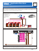
Application A 274-7
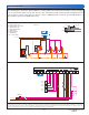
Concept Drawing: This is only a concept drawing, not an engineered drawing. It is not intended to describe a complete system, nor any particular system. It is up to the
system designer to determine the necessary components for and configuration of the particular system being designed, including additional equipment, isolation relays
(for loads greater than the control’s specified output ratings), and any safety devices which in the judgement of the designer are appropriate, in order to properly size,
configure and design that system and to ensure compliance with building and safety code requirements.
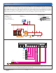
Electrical
System Description:
The Boiler Control 274 operates two On/Off boilers and boiler pumps piped in primary-secondary,
providing outdoor reset for the space heating zones. When a valid DHW Demand is present, the DHW pump P3 turns on.
The boiler supply temperature for the indirect tank is measured by sensor S3. There are two boiler target temperatures,
one for the heating system (Boil TARG) and one for the indirect DHW system (DHW TARG). DHW Demand is provided by
an external aquastat or tN4 DHW control. The 274 has a combustion air contact which closes and opens a damper when a
boiler is to fire. A combustion air proof ensures the damper is open before firing a boiler. The 274 receives a boiler demand
from the regular thermostats through the external relays.
Mechanical
S1 = Outdoor Sensor 070
S2 = Boiler Supply Sensor 082
S3 = DHW Sensor 082
A1 = DHW Aquastat
A2 = High Limit Aquastat
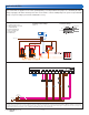
S2
S3
R1 R2
S1 M1 C1
P1 P2
A1
P3
P4 P5
120 V (ac)
24 V (ac)
Class 2
Transformer
274
A2
P1 P2
S2S1 S3
Boiler
1
P3
C
24V(ac)
R
N
115 V (ac)
Class 2
Transformer
L
M
C1
M1
A1A2
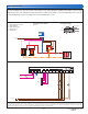
7
8
1
2
6
5
4
3
P5
P4
R1 R2
tekmar 500 Series
Thermostat
RC
Relay 1
tekmar 500 Series
Thermostat
RC
Relay 1
7
8
1
2
6
5
4
3
Boiler
2
6
DHW
5
4
Sup
3
+
2
-
1
Do not apply power
274
N
720
Power
L
8
tN4 Com Out Boil Com BRet/ Relay
1
910
Relay
2
11 12
Relay
3
13 14
Relay
4
15 16
C.A./
Alert
21 22
Boiler
Demand
23 24
DHW
/Setp
Com
Dem
25
Pr.
Dem
19
Prim
P1
18
DHW
/P2
17
Demands
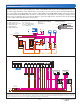
Setback
Off
EMS
Rotate
Fixed Last
Pump Sequencer
Exercise
Off
Fixed Lead
First On / Last Off
First On / First Off
274 Switch Settings:Essential Control Settings:
Mode = 2
DHW Mode = 5
C1 = C.A, Proof
M1 - C.A. Damper Motor
P1 & P2 = Boiler Pumps
P3 = DHW Pump