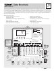
- Data Brochure D 268 Boiler Control 268 11/10 The tekmar Boiler Control 268 can control the supply water temperature from up to 9 on / off stages based on outdoor temperature, control for Domestic Hot Water (DHW) generation, a setpoint requirement or optionally an external input signal (0 - 10 V (dc)). A large easy to read display provides current system temperatures and operating status. The control has outputs for a primary pump and either a combustion air damper or alert.
How To Use The Data Brochure This brochure is organized into four main sections. They are: 1) Sequence of Operation, 2) Installation, 3) Control Settings, and 4) Testing and Troubleshooting. The Sequence of Operation section has seven sub-sections. We recommend reading Section A: General of the Sequence of Operation, as this contains important information on the overall operation of the control. Then read the sub sections that apply to your installation.
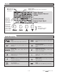
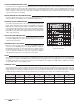
Display Menu Field Displays the current menu Number Field Displays the current value of the selected item Boiler Demand DHW / Setpoint Demand WWSD Item Field Displays an abbreviated name of the selected item Priority Override External Input Signal Offset Status Field Displays the current status of the control's inputs, outputs and operation Buttons Selects Menus, Items and adjust settings Symbol Description Stage Displays which stage relays are turned on.
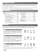
Definitions The following defined terms and symbols are used throughout this manual to bring attention to the presence of hazards of various risk levels, or to important information concerning the life of the product. - Warning Symbol: Indicates presence of hazards which can cause severe personal injury, death or substantial property damage if ignored.
SETBACK (UNOCCUPIED) 1 2 3 4 5 l Out UnO Com Boil Boi Sw Sup Ret To provide greater energy savings, the control has a setback feature. With setback, the supply water temperature in the system is reduced when the building is unoccupied. By reducing the supply water temperature, the air temperature in the space may be reduced even when thermostat(s) are not turned down. Any time the UnO Sw (5) and the Com – (1) are shorted together, the control operates in the UnOccupied mode.
RUNNING TIMES The control displays the accumulated running time of each boiler in the VIEW menu. When using a multi-stage boiler, the running time that is displayed is the total number of running hours of the Lo stage of the boiler. Resetting the Running Times To reset the running time for each boiler, select the appropriate running time in the VIEW menu. Next press the ▲ and ▼ buttons simultaneously until CLR is displayed.
RELAY 1 RELAY 2 RELAY 3 RELAY 4 RELAY 5 RELAY 6 RELAY 7 RELAY 8 RELAY 9 MODE 1 Boiler 1 Boiler 2 Boiler 3 Boiler 4 Boiler 5 Boiler 6 Boiler 7 Boiler 8 Boiler 9 MODE 2 Boiler 1 Boiler 1 Pump Boiler 2 Boiler 2 Pump Boiler 3 Boiler 3 Pump Boiler 4 Boiler 4 Pump ––– MODE 3 Boiler 1 Stage 1 Boiler 1 Stage 2 Boiler 2 Stage 1 Boiler 2 Stage 2 Boiler 3 Stage 1 Boiler 3 Stage 2 Boiler 4 Stage 1 Boiler 4 Stage 2 ––– MODE 4 Boiler 1 Stage 1 Boiler 1 Stage 2 Boiler 1 Pump Boil
BOILER MASS The BOIL MASS setting allows the installer to adjust the control to the thermal mass of the type of heat sources used in the application. The BOIL MASS setting also adjusts the minimum inter-stage delay time when operating with an automatic differential. Lo (1) The Lo setting is selected if the boiler(s) that is used has a low thermal mass. This means that the boiler(s) has a very small water content and has very little metal in the heat exchanger.
Primary Pump Purge After a demand is removed, the control continues to operate the primary pump for a period of time. The maximum length of time that the primary pump continues to run is adjustable using the Purge setting. The primary pump continues to run until either the purging time has elapsed or the boiler supply temperature drops more than a differential below the boiler minimum setting.
CHARACTERIZED HEATING CURVE The control varies the supply water temperature based on the outdoor air temperature. The control takes into account the type of terminal unit that the system is using. Since different types of terminal units transfer heat to a space using different proportions of radiation, natural convection and forced convection, the supply water temperature must be controlled differently.
High Mass Radiant (1) This type of a hydronic radiant floor is embedded in either a thick concrete or gypsum pour. This heating system has a large thermal mass and is slow acting. Low Mass Radiant (2) This type of radiant heating system is either attached to the bottom of a wood sub-floor, suspended in the joist space, or sandwiched between the sub-floor and the surface. This type of radiant system has a relatively low thermal mass and responds faster than a high mass system.
Section E: Domestic Hot Water Operation Section E1 DHW Section E1: Domestic Hot Water (DHW) DHW DEMAND A DHW Demand is required in order for the control to provide heat to the DHW system. A DHW aquastat or setpoint control is used as a switch in the DHW demand circuit. Once the control detects a DHW demand, the DHW Demand pointer turns on in the LCD and the control operates the boiler to provide a sufficient boiler supply water temperature to the DHW tank. The control operates the pumps as described below.
DHW MODE 4 – DHW in Primary / Secondary with Priority Disable Using External Wiring When a DHW Demand is present, the Relay 9 / DHW contact (terminals 30 and 31) is closed and the primary pump contact is closed. Priority can only be obtained using external wiring. During a priority override, the Relay 9 / DHW contact is opened until the heating system has recovered before returning to DHW operation. This mode can be used if a DHW tank is piped in direct return and a DHW valve is installed.
Section E2: DHW with Low Temperature Boilers If DHW is to be incorporated into a low temperature system such as a radiant heating system, a mixing device is often installed to isolate the high DHW supply temperature from the lower system temperature. If a mixing device is not installed, high temperature water could be supplied to the low temperature system while trying to satisfy the DHW demand. This may result in damage to the low temperature heating system.
Section F: Setpoint Operation Section F1 Setpoint Section F1: Setpoint Setpoint operation is only available when DHW MODE is set to OFF. SETPOINT The control can operate to satisfy the requirements of a setpoint load in addition to a space heating load. A setpoint load overrides the current outdoor reset temperature and WWSD setting in order to provide heat to the setpoint load. 7 8 SETPOINT DEMAND A setpoint demand is required in order for the control to provide heat to the setpoint load.
Section G: External Input Operation Section G1 External Input Section G1: External Input EXTERNAL INPUT The control can accept an external DC signal in place of the outdoor sensor. The control converts the DC signal into the appropriate boiler target temperature between 50°F (10°C) and 210°F (99°C) based on the External Input Signal and Offset settings. To use the external input signal, the External Input / Stand Alone DIP switch must be set to External Input.
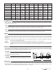
External Input Signal Conversion Tables CONVERSION TABLE 2 - 10 CONVERSION TABLE 0 - 10 0 - 20 mA* 0 - 10 V (dc) Boiler Target 4 - 20 mA* 2 - 10 V (dc) Boiler Target 0 0 – – – (OFF) 0 0 – – – (OFF) 2 1 50°F (10°C) 4 2 50°F (10°C) 4 2 68°F (20°C) 6 3 70°F (21°C) 6 3 86°F (30°C) 8 4 90°F (32°C) 8 4 103°F (39°C) 10 5 110°F (43°C) 10 5 121°F (49°C) 12 6 130°F (54°C) 12 6 139°F (59°C) 14 7 150°F (66°C) 14 7 157°F (69°C) 16 8 170°F (77°C) 16 8 174°F (79°C)
Power must not be applied to any of the wires during the rough-in wiring stage. • • All wires are to be stripped to a length of 3/8” (9 mm) to ensure proper connection to the control. If an Outdoor Sensor 070 is used, install the sensor according to the installation instructions in the Data Brochure D 070 and run the wiring back to the control. • Install the Boiler Supply Sensor 082 according to the installation instructions in the Data Brochure D 070 and run the wiring back to the control.
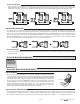
Output Connections 11 9 10 Prim Primary Pump Contact (Prim P1) Power L N The Prim P1 output terminal (11) is a powered output. When the relay in the control closes, 115 V (ac) is provided to the Prim P1 terminal (11) from the Power L terminal (10). To operate the primary pump, connect one side of the primary pump circuit to terminal 11 and the second side of the pump circuit to the neutral (N) side of the 115 V (ac) power supply. 115 V (ac) N L Combustion Air / Alert Contact (C.A.
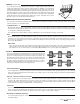
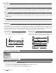
UnOccupied Switch If an external timer (tekmar Timer 032) or switch is used, connect the two wires from the external switch to the Com – and UnO Sw terminals (1 and 5). When these two terminals are shorted together, the control registers an UnOccupied signal. STEP FIVE —————— 1 2 3 4 5 l Out UnO Com Boil Boi Sw Sup Ret TESTING THE WIRING General Each terminal block must be unplugged from its header on the control before power is applied for testing.
4 1 2 3 Out V External Input Boil Com Boil Ret – Sup If an external input is used, measure the voltage between the Com – and the Out + terminals (1 and 4). When the external input device calls for heat, you should measure between 0 and 10 V (dc) at the terminals.
Connecting The Control Make sure all power to the devices and terminal blocks is off, and remove any remaining jumpers from the terminals. 1 2 3 Boil Com Boil Ret Sup Reconnect the terminal blocks to the control by carefully aligning them with their respective headers on the control, and then pushing the terminal blocks into the headers. The terminal blocks should snap firmly into place.
Rotate / Off The Rotate / Off DIP switch selects whether or not the control is to provide Equal Run Time Rotation of the boiler stages. If the switch is set to Rotate, the stages will be rotated accordingly. If the switch is set to Off, the firing sequence is fixed starting with the lowest stage to the highest stage. Fixed Last / Off The Fixed Last / Off DIP switch selects whether or not the last boiler is to be included in the rotation sequence.
Display Se c In tio st n Ad alle va r nc ed View Menu (1 of 2) Description Outdoor - Current outdoor air temperature as measured by the outdoor sensor. This item is only available if the External Input/Stand Alone DIP switch is set to Stand Alone. This item is available in all modes. Boiler Supply - Current boiler supply water temperature as measured by the boiler supply sensor. This item is available in all modes.
Display Se c In tio st n Ad alle va r nc ed View Menu (2 of 2) A 7 A 8 A 9 Description Range Boiler 7 Hours - The total running time of boiler 7 since this item was last cleared. 0 to 1999 hr To clear this item, press the ▲ and ▼ button simultaneously while viewing this item. This item is available in mode 1 only. Boiler 8 Hours - The total running time of boiler 8 since this item was last cleared. 0 to 1999 hr To clear this item, press the ▲ and ▼ button simultaneously while viewing this item.
Display Se c In tio st n Ad alle va r nc ed Adjust Menu (2 of 4) Description Range B1 Boiler 2 - Selects whether or not boiler 2 is operational. This item is available in modes 1 to 7. Au (Auto), OFF Default = Au B1 Boiler 3 - Selects whether or not boiler 3 is operational. This item is available in modes 1 to 5. Au (Auto), OFF Default = Au B1 Boiler 4 - Selects whether or not boiler 4 is operational. This item is available in modes 1 to 3.
Display Se c In tio st n Ad alle va r nc ed Adjust Menu (3 of 4) Description Range A Boiler Minimum - The minimum allowed boiler target temperature. OFF, 80 to 180°F (OFF, 27 to 82°C) Default = 140°F (60°C) A Boiler Maximum - The maximum allowed boiler target temperature.
Display Se c In tio st n Ad alle va r nc ed Adjust Menu (4 of 4) Description Range 1 to Max number of boilers Default = Maximum number of boilers E1 DHW Boilers Selects how many boilers are to be operated during DHW generation. (This item is only available when the last boiler in MODES 1, 4, and 5 is set to OFF and DHW MODE is set to 1 through 4.) F1 1 (parallel, no priority), Setpoint Mode Selects the Setpoint Mode of operation.
Testing the Control The control has a built-in test routine that is used to test the main control functions. The control continually monitors the sensors and displays an error message whenever a fault is found. See the following pages for a list of the control’s error messages and possible causes. When the Test button is pressed, the test light is turned on. The individual outputs and relays are tested in the following test sequence. TEST SEQUENCE Each step in the test sequence lasts 10 seconds.
Error Messages The control was unable to read a piece of information stored in its memory. Because of this, the control was required to reload the factory settings into all of the items in the ADJUST menu. The control will stop operation until all of the items in the ADJUST menu of the control have been checked by the user or installer. Note: The Installer / Adv DIP Switch must be set to Adv in order to clear the error. The control is no longer able to read the outdoor sensor due to a short circuit.
Notes 31 of 32 © 2010 D 268 - 11/10
Technical Data Boiler Control 268 Nine Stage Boiler & DHW / Setpoint — — — — — Ambient conditions Power supply Relay capacity Demands Sensors included — — — — — Optional devices — D 268, A 268’s, D 001, D 070. Microprocessor PID control; This is not a safety (limit) control. 3.3 lb. (1500 g), Enclosure A, blue modified PPO plastic 6-5/8” H x 7-9/16” W x 2-13/16” D (170 x 193 x 72 mm) CSA C US, CSA 22.2 No 24 and UL 873, meets class B: ICES & FCC Part 15.