
Application Brochure


1 of 8
- Application
Boiler Control 261
A 261-1
03/09
Copyright ©2009 A 261-1 03/09
Note:
This is only a concept drawing. The designer must determine whether this application will work in his system and must ensure compliance with
code requirements. Necessary auxiliary equipment, isolation relays (for loads greater than the specified tekmar internal relay ratings), and other safety
and limit devices must be added.
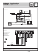
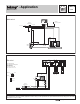
Electrical
P1 = Boiler Pump
S1 = Boiler Sensor 082
S2 = Outdoor Sensor 070
U1 = tekmar Timer 033 (optional)
V1 = Balancing Valve or Pressure Bypass Valve
S1
S2
U1
N
L
120 V (ac)
P1
261
12 4
6
8
10
5 9
Do not apply power
11 12 13 14 15
Sw
UnO
7
N
L
N
Power
1716
Com
Out
3
10A
Boiler
Demand
Setpoint
Demand
Boil
Pmp
Stage
Stage
Boil
Com
10A 10A
1122
Boiler
#1
Boiler
#2
Mechanical
T
TT
P1
T
Outdoor
Sensor (S2) 070
Boiler
Sensor
(S1) 082
∆P
120 V (ac)
261
V1
Return
Installer
Off
Rotate
Advanced
= Required
= Optional