
User Guide


1 of 8
- Application
Boiler Control 260
A 260-1
03/09
Copyright ©2009 A 260-1 03/09
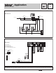
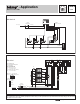
Note:
This is only a concept drawing. The designer must determine whether this application will work in his system and must ensure compliance with
code requirements. Necessary auxiliary equipment, isolation relays (for loads greater than the specified tekmar internal relay ratings), and other safety
and limit devices must be added.
P1
M
M
M
T3
T2
T1
Outdoor
Sensor (S2) 070
Boiler
Sensor
(S1) 082
Z1Z2Z3
Class 2
Transformer
120 V (ac)
24 V (ac)
260
Mechanical
N
L
Zone Valve
Motor End
Switches
U1
S1
S2
Boiler
260
12468 10 11
Boiler
Demand
LN
3
Power
5
9
Boil
Do not apply power
13 14 15 16 17 18
Com
Sw
UnO
Com
Boil
Out
12
Indr
DHW
Demand
7
P1 N
DHW
Pmp/Vlv
Boiler
10A
10A10A
24 V (ac)
120 V (ac)
Class 2
Transformer
C
R
P1
Z1
Z2
Z3
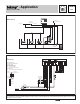
Electrical
P1 = Boiler Pump
S1 = Boiler Sensor 082
S2 = Outdoor Sensor 070
T1, ..., T3 = Thermostats
U1 = tekmar Timer 033 (optional)
Z1, ..., Z3 = Zone Valve Motor End Switches
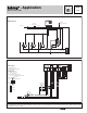
Off
Installer
Advanced
DHW during UnOcc
DHW Pump
Off
DHW Priority
DHW Valve
= Not Used
= Required
= Optional